20-COMM-M Modbus/TCP Adapter Firmware 1.
Important User Information Solid state equipment has operational characteristics differing from those of electromechanical equipment. Safety Guidelines for the Application, Installation and Maintenance of Solid State Controls (Publication SGI-1.1 available from your local Rockwell Automation sales office or online at http:// www.rockwellautomation.com/literature) describes some important differences between solid state equipment and hard-wired electromechanical devices.
Summary of Changes The information below summarizes the changes made to this manual since its last release (March 2010): Description of Changes In the subsection “Direct Access Method,” added a TIP to determine the starting register for a 0-based Modbus/TCP master device, and the registers to read for the example provided.
soc-ii Summary of Changes 20-COMM-M Modbus/TCP Adapter User Manual Publication 20COMM-UM014C-EN-P
Table of Contents Preface About This Manual Related Documentation . . . . . . . . . . . . . . . . . . . . . . . . . . . . . . . . . . . . . . . . . . . . . . . . . . P-1 Rockwell Automation Support . . . . . . . . . . . . . . . . . . . . . . . . . . . . . . . . . . . . . . . . . . . . . P-2 Conventions Used in This Manual . . . . . . . . . . . . . . . . . . . . . . . . . . . . . . . . . . . . . . . . . . P-2 Chapter 1 Getting Started Components. . . . . . . . . . . . . . . . . . . . . . . . . . . . . . .
ii Table of Contents Chapter 5 Troubleshooting Understanding the Status Indicators . . . . . . . . . . . . . . . . . . . . . . . . . . . . . . . . . . . . . . . . . PORT Status Indicator . . . . . . . . . . . . . . . . . . . . . . . . . . . . . . . . . . . . . . . . . . . . . . . . . . . . MOD Status Indicator . . . . . . . . . . . . . . . . . . . . . . . . . . . . . . . . . . . . . . . . . . . . . . . . . . . . NET A Status Indicator . . . . . . . . . . . . . . . . . . . . . . . . . . . . . . . . . . .
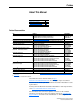
Preface About This Manual Topic Related Documentation Rockwell Automation Support Conventions Used in This Manual Page P-1 P-2 P-2 Related Documentation For: EtherNet/IP Refer to: EtherNet/IP Media Planning and Installation Manual (1) EtherNet/IP Network Infrastructure Guidelines (1) EtherNet/IP Performance and Application Guide DriveExplorer™ http://www.ab.com/drives/driveexplorer, and DriveExplorer online help (2) DriveTools™ SP (includes DriveExecutive™) http://www.ab.
P-2 About This Manual Rockwell Automation Support Rockwell Automation, Inc. offers support services worldwide, with over 75 sales/support offices, over 500 authorized distributors, and over 250 authorized systems integrators located through the United States alone. In addition, Rockwell Automation, Inc. representatives are in every major country in the world. Local Product Support Contact your local Rockwell Automation, Inc.
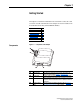
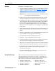
Chapter 1 Getting Started The adapter is intended for installation into a PowerFlex 7-Class drive and is used for network communication. The adapter can also be installed in an External DPI Comms Kit (20-XCOMM-DC-BASE). Topic Components Features Compatible Products Required Equipment Safety Precautions Quick Start Status Indicators Components Figure 1.
1-2 Getting Started Features The features of the adapter include: • Typical mounting in a PowerFlex 7-Class drive. The adapter can also be installed in a DPI External Comms Kit. See Chapter 7, Installing the Adapter in a DPI External Comms Kit (20-XCOMM-DC-BASE) for more information. Important: Due to inherent operating limitations, the adapter cannot be used with the kit’s optional I/O board.
Getting Started Required Equipment 1-3 Equipment Shipped with the Adapter When you unpack the adapter, verify that the package includes: ❑ One adapter ❑ A 2.54 cm (1 in.) and a 15.24 cm (6 in.) Internal Interface cable (only one cable is needed to connect the adapter to the drive; for which cable to use, see Figure 2.
1-4 Getting Started ! ! ! ! ! ! ATTENTION: Risk of injury or equipment damage exists. If the adapter is transmitting control I/O to the drive, the drive may fault when you reset the adapter. Determine how your drive will respond before resetting an adapter. ATTENTION: Risk of injury or equipment damage exists. Parameter 23 - [Comm Flt Action] lets you determine the action of the adapter and connected drive if communications are disrupted. By default, this parameter faults the drive.
Getting Started Quick Start 1-5 This section is provided to help experienced users quickly start using the adapter. If you are unsure how to complete a step, refer to the referenced chapter. Step 1 2 3 4 5 Action Review the safety precautions for the adapter. Verify that the PowerFlex drive is properly installed. Install the adapter. Refer to… Throughout This Manual Drive User Manual PowerFlex 7-Class DPI Network Communication Verify that the PowerFlex drive is not powered.
1-6 Getting Started Status Indicators The adapter uses four status indicators to report its operating status. They can be viewed on the adapter or through the drive cover (Figure 1.2). Figure 1.2 Status Indicators (location on drive may vary) ➊ ➋ ➌ ➍ ➊ ➋ ➌ ➍ Item Name ➊ PORT ➋ ➌ ➍ MOD NET A NET B After installing the adapter and applying power to the drive, refer to Start-Up Status Indications on page 2-6 for possible start-up status indications and their descriptions.
Chapter 2 Installing the Adapter This chapter provides instructions for installing the adapter in a PowerFlex 7-Class drive. This adapter can also be installed in a DPI External Comms Kit. In this case, refer to the 20-XCOMM-DC-BASE Installation Instructions (publication 20COMM-IN001) supplied with the kit.
2-2 Installing the Adapter Setting the Web Pages Switch To use the adapter web pages, the Web Pages Switch must be set to its “Enable Web” position. Important: A new switch setting is recognized only when power is applied to the adapter, or the adapter is reset. If you change a switch setting, cycle power or reset the adapter to apply the change. Set the Web Pages Switch SW2 (Figure 2.1) to enable or disable the adapter web pages. By default, the adapter web pages are disabled.
Installing the Adapter Connecting the Adapter to the Drive ! 2-3 ATTENTION: Risk of injury or death exists. The PowerFlex drive may contain high voltages that can cause injury or death. Remove power from the drive, and then verify power has been discharged before installing or removing the adapter. 1. Remove power from the drive. 2. Use static control precautions. 3. Remove the drive cover or open the drive door. 4.
2-4 Installing the Adapter Figure 2.2 DPI Ports and Internal Interface Cables 20-COMM-M Adapter ➊ ➋ ➌ PowerFlex 70 - All Frames ➍ PowerFlex 700 Frames 0 and 1 PowerFlex 700S Frames 0 and 1 PowerFlex 700 Frames 2 and Larger PowerFlex 700S Frames 2 through 6 HIM panel opens to allow access to DPI interface. To open panel, remove screws on left side of HIM panel and swing open.
Installing the Adapter Figure 2.3 2-5 Mounting and Grounding the Adapter Drive 0.9 N•m (8.0 lb•in) 4 Places Adapter Internal Interface Cable folded behind the adapter and in front of the drive. Ground Tab Detail PowerFlex 70 - All Frame Sizes (Adapter mounts in drive.) 0.9 N•m (8.0 lb•in) 4 Places PowerFlex 700 Frames 0 and 1 PowerFlex 700S Frames 0 and 1 (Adapter mounts on door.) Verify metal ground tab is bent 90° and is under the adapter before tightening screw.
2-6 Installing the Adapter Connecting the Adapter to the Network ! ATTENTION: Risk of injury or death exists. The PowerFlex drive may contain high voltages that can cause injury or death. Remove power from the drive, and then verify power has been discharged before installing or removing the adapter. 1. Remove power from the drive. 2. Use static control precautions. 3. Connect one end of an Ethernet cable to the network. See Figure 2.4 for an example of wiring to a Modbus/TCP network. Figure 2.
Installing the Adapter Figure 2.5 2-7 Drive and Adapter Status Indicators (location on drive may vary) PORT MOD ➋ NET A NET B ➊ STS Table 2.A Drive and Adapter Start-Up Status Indications Item Name Color ➊ Green STS (Status) Yellow Red ➋ PORT Green MOD Green NET A Green NET B Green State Description Drive STS Indicator Flashing Drive ready but not running, and no faults are present. Steady Drive running, no faults are present.
2-8 Installing the Adapter Configuring/Verifying Key Drive Parameters The PowerFlex 7-Class drive can be separately configured for the control and Reference functions in various combinations. For example, you could set the drive to have its control come from a peripheral or terminal block with the Reference coming from the network. Or you could set the drive to have its control come from the network with the Reference coming from another peripheral or terminal block.
Chapter 3 Configuring the Adapter This chapter provides instructions and information for setting the parameters to configure the adapter.
3-2 Configuring the Adapter Using the PowerFlex 7-Class If your drive has either an LED or LCD HIM (Human Interface Module), it can be used to access parameters in the adapter as shown below. It is HIM recommended that you read through the steps for your HIM before performing the sequence. For additional information, refer to your PowerFlex Drive User Manual or the PowerFlex 7-Class HIM Quick Reference (publication 20HIM-QR001). Using an LED HIM Step 1.
Configuring the Adapter Using BOOTP 3-3 By default, the adapter is configured so that you can set its IP address, subnet mask, and gateway address by using a BOOTP utility. You can select from a variety of BOOTP utilities. These instructions use Rockwell’s BOOTP Server (version 2.3 or higher), a stand-alone program that incorporates the functionality of standard BOOTP utilities with a graphical interface. It is available from http://www.software.rockwell.com/support/ download/detail.cfm?ID=3390.
3-4 Configuring the Adapter Figure 3.2 Network Settings Window 4. Edit the following: Box Subnet Mask (1) Gateway (1) Primary DNS Type The subnet mask for the adapter’s network. The IP address of the gateway device on the adapter’s network. The address of the primary DNS server to be used on the local end of the link for negotiating with remote devices.
Configuring the Adapter 3-5 8. Click OK to apply the settings. The adapter appears in the Relation List (Figure 3.4) with the new settings. Figure 3.4 BOOTP Server Window with Adapter in the Relation List 9. To assign this configuration to the adapter permanently, select the device in the Relation List and click Disable BOOTP/DHCP. When power is cycled on the adapter, it will use the configuration you assigned it and not issue new BOOTP requests.
3-6 Configuring the Adapter Setting the IP Address, Subnet Mask, and Gateway Address By default, the adapter is configured so that you set its IP address, subnet mask, and gateway address using a BOOTP server. If you want to set these attributes using the adapter parameters instead, you must disable BOOTP and then set the appropriate parameters in the adapter. Disabling the BOOTP Feature 1. Set the value of Parameter 03 - [BOOTP] to “0” (Disabled). Figure 3.
Configuring the Adapter 3-7 Setting a Subnet Mask Using Parameters 1. Verify that Parameter 03 - [BOOTP] is set to “0” (Disabled). This parameter must be set to Disabled to configure the subnet mask using the adapter parameters. 2. Set the value of Parameters 08 - [Subnet Cfg 1] through 11 - [Subnet Cfg 4] to the desired value for the subnet mask. Figure 3.7 Example Subnet Cfg 1 LCD HIM Screen Default = 0.0.0.0 Port 5 Device 20-COMM-M Parameter #: 08 Subnet Cfg 1 0 0 <> 255 255 . 255 . 255 .
3-8 Configuring the Adapter Setting the Data Rate By default, the adapter is set to autodetect, so it automatically detects the data rate and duplex setting used on the network. If you need to set a specific data rate and duplex setting, the value of Parameter 16 - [EN Rate Cfg] determines the Ethernet data rate and duplex setting that the adapter will use to communicate. For definitions of data rate and duplex, refer to the Glossary. 1.
Configuring the Adapter 3-9 3. If you enabled one or more Datalinks, configure parameters in the drive to determine the source and destination of data in the Datalink(s). For example, configure the Datalinks in PowerFlex 70 and 700 drives by setting Parameters 300 - [Data In A1] through 317 - [Data Out D2]. Also, ensure that the Modbus/TCP adapter is the only adapter using the enabled Datalink(s). 4. Reset the adapter (see Resetting the Adapter on page 3-12). The adapter is ready to receive I/O.
3-10 Configuring the Adapter Setting the Fault Configuration Parameters If you set Parameter 23 - [Comm Flt Action] to “Send Flt Cfg,” the values in the following parameters are sent to the drive after an I/O communications fault and/or idle fault occurs. You must set these parameters to values required by your application. Parameter 26 - [Flt Cfg Logic] 27 - [Flt Cfg Ref] 28 - [Flt Cfg x1 In] through 35 - [Flt Cfg x2 In] Description A 16-bit value sent to the drive for Logic Command.
Configuring the Adapter 3-11 Setting Web Access Control By using a web browser to access the IP address set for the adapter, you can view the adapter’s web pages for information about the adapter, its connected drive, and other DPI devices connected to the drive, such as HIMs or converters.
3-12 Configuring the Adapter Resetting the Adapter Changes to switch settings and some adapter parameters require that you reset the adapter before the new settings take effect. You can reset the adapter by power cycling the drive or by using Parameter 22 - [Reset Module]. ! ATTENTION: Risk of injury or equipment damage exists. If the adapter is transmitting control I/O to the drive, the drive may fault when you reset the adapter.
Configuring the Adapter Flash Updating the Adapter 3-13 The adapter can be flash updated over the network or serially through a direct connection from a computer to the drive using a 1203-USB or 1203-SSS serial converter. When flashing over the network, you can use the Allen-Bradley software tool ControlFLASH, the built-in flash capability of DriveExplorer Lite or Full, or the built-in flash capability of DriveExecutive.
3-14 Configuring the Adapter Notes: 20-COMM-M Modbus/TCP Adapter User Manual Publication 20COMM-UM014C-EN-P
Chapter 4 Using Modbus/TCP Function Codes This chapter provides information about controlling a PowerFlex 7-Class drive, setting its Reference, and accessing its parameters and the parameters of its connected peripherals using Modbus/TCP Function Codes over the Modbus/TCP network.
4-2 Using Modbus/TCP Function Codes Supported Modbus/TCP Function Codes On Modbus/TCP, a register is defined as an addressable container that holds 16-bit data. All parameters (16-bit or 32-bit) for the drive and its connected peripherals always occupy two consecutive 16-bit registers—one for the Lo Word and one for the Hi Word—even if the parameter is only a 16-bit word. In this case, the parameter value is the Lo Word. The adapter supports the Modbus/TCP function codes listed in Table 4.A. Table 4.
Using Modbus/TCP Function Codes Unit Identifier 4 5 6 7…15 16 17…254 255 4-3 Device Connection (Example) DPI Port 4 (peripheral connected to Port 4 of a four-way splitter cable) DPI Port 5 (peripheral connected to the drive’s internal Port 5 or to Port 5 of a four-way splitter cable) DPI Port 6 (reserved for future use) Reserved for future use DPI Port 0 (Drive) — an alternate to using Unit Identifier 0 Unused — defaults to Unit Identifier 0 Adapter Using Function Code 43 to Read Drive Identification Fu
4-4 Using Modbus/TCP Function Codes Peripheral Status Register (Address 10022) The Peripheral Status register contains information on which DPI Ports presently have a peripheral connected and logged into the drive according to Table 4.C. By using Function Code 03 or 23, you can read register address 10022 to conveniently determine which DPI Ports and peripherals are in use. Table 4.
Using Modbus/TCP Function Codes 4-5 Table 4.D Logic Command Registers (to Drive from Controller) Register Address 1 2 3 4 5 6 7 8 9 10 11 12 13 14 15 16 (1) (2) Logic Command PowerFlex 70/700 Example Bit Description Values 0 Stop 0 = Not Stop 1 = Stop 0 = Not Start 1 Start (1) (2) 1 = Start 2 Jog 0 = Not Jog (Par.
4-6 Using Modbus/TCP Function Codes Table 4.F Reference Registers Register Address 10003 (1) 10004 (1) Description Values Reference Lo Reference Hi Bit 0…15 of 32-bit Reference or the whole 16-bit Reference Bit 16…31 of 32-bit Reference For a 16-bit Reference, you must write the complete 32-bit value. The Reference value is a scaled engineering value; it is NOT in Hertz or RPM. The Reference uses a “32767” scale.
Using Modbus/TCP Function Codes 4-7 Speed Feedback uses the same scaling as the speed Reference. TIP: For PowerFlex 700 VC drives (firmware v3.xxx or higher), Parameter 299 - [DPI Fdbk Select] enables you to select the feedback data coming from the drive over DPI. The default is “Speed Fdbk” in Hz or RPM determined by Parameter 079 - [Speed Units].
4-8 Using Modbus/TCP Function Codes Table 4.G Logic Status Registers (to Controller from Drive) (Continued) Register Address 10 11 12 13 14 15 16 Logic Status Bit PowerFlex 70/700 Example Description Values 9 Local Control Register Address 10 12 11 10 11 0 0 0 = Port 0 (TB) 0 0 1 = Port 1 0 1 0 = Port 2 0 1 1 = Port 3 1 0 0 = Port 4 1 0 1 = Port 5 1 1 0 = Port 6 1 1 1 = No Local 12 Reference Register Address 13 16 15 14 13 14 0 0 0 0 = Ref A Auto (Par. 90) 15 0 0 0 1 = Ref B Auto (Par.
Using Modbus/TCP Function Codes Accessing Device Parameters 4-9 There are two methods for accessing parameters in the drive or its connected peripherals: the direct access method (for individual or contiguous parameters) and the indirect access method (for contiguous or non-contiguous parameters). Direct Access Method ! ATTENTION: Risk of equipment damage exists.
4-10 Using Modbus/TCP Function Codes Indirect Access Method ! ATTENTION: Risk of equipment damage exists. When adapter Parameters 38 - [Indirect Par #1] through 53 - [Indirect Par #16] and their corresponding data registers are used to write parameter data to Non-Volatile Storage (NVS) frequently, the NVS will quickly exceed its life cycle and cause the drive to malfunction. Do not create a program that frequently uses Indirect Parameters to write parameter data to NVS.
Using Modbus/TCP Function Codes 4-11 Reading Device Parameters 1. Verify that the Unit Identifier is set to “0” (zero) or “16.” 2. Using Table 4.J and its associated formula, determine the value to use for an adapter Indirect Par #x that points to the specific device parameter you want to read. For example, suppose adapter Parameter 38 - [Indirect Par #1] is used and you want to read drive Parameter 003 - [Output Current] or drive Parameter 012 - [DC Bus Voltage].
4-12 Using Modbus/TCP Function Codes Writing Device Parameters 1. Verify that the Unit Identifier is set to “0” (zero). 2. Using Table 4.J and its associated formula, determine the value to use for an adapter Indirect Parameter that points to the specific device parameter you want to write. For example, suppose adapter Parameter 38 - [Indirect Par #1] is used and you want to write to drive Parameter 140 - [Accel Time 1]. In this case, set adapter Parameter 38 - [Indirect Par #1] to a value of “140.” 3.
Using Modbus/TCP Function Codes 4-13 Table 4.
4-14 Using Modbus/TCP Function Codes Using 16-Bit Datalinks to Read/Write 32-Bit Parameters This subsection only pertains to PowerFlex 70 (SC or EC), PowerFlex 700 (SC), and PowerFlex 700H drives which use 16-bit Datalinks. To read or write a 32-bit parameter using 16-bit Datalinks, typically both Datalinks of a pair (A, B, C, D) are set to the same 32-bit parameter. For example, to read Parameter 10 - [Elapsed Run Time] in a PowerFlex 70 drive, both Datalink A1 Out and Datalink A2 Out are set to “10.
Using Modbus/TCP Function Codes Supported Modbus Registers 4-15 The adapter supports the Modbus registers listed in Table 4.N. Table 4.
4-16 Using Modbus/TCP Function Codes Modbus Register 4x10019 4x10020 4x10021 4x10022 4x10023 4x10024 4x10025 4x10026 4x10027 4x10028 4x10029 4x10030 4x10031 4x10032 4x10033 4x10034 4x10035 4x10036 4x10037 4x10038 4x10039 4x10040 4x10041 4x10042 4x10043 4x10044 4x10045 4x10046 4x10047 4x10048 4x10049 4x10050 4x10051 4x10052 4x10053 4x10054 4x10055 4x10056 4x10057 4x10058 4x10059 4x10060 4x10061 4x10062 4x10063 4x10064 4x10065 4x10066 4x10067 4x10068 4x10069 4x10070 4x10071 4x10072 20-COMM-M Modbus/TCP Ada
Chapter 5 Troubleshooting This chapter provides information for diagnosing and troubleshooting potential problems with the adapter and network. Topic Understanding the Status Indicators PORT Status Indicator MOD Status Indicator NET A Status Indicator NET B Status Indicator Viewing Adapter Diagnostic Items Viewing and Clearing Events Understanding the Status Indicators Page 5-1 5-2 5-2 5-3 5-3 5-4 5-6 The adapter has four status indicators. They can be viewed on the adapter or through the drive cover.
5-2 Troubleshooting PORT Status Indicator Status Off Flashing Red Steady Red This red/green bicolor LED indicates the status of the adapter’s connection to the drive as shown in the table below. Cause The adapter is not powered or is not properly connected to the drive. Corrective Action • Securely connect the adapter to the drive using the Internal Interface (ribbon) cable. The adapter is not receiving a ping message from the drive.
Troubleshooting NET A Status Indicator Status Off Steady Red Flashing Red 5-3 This red/green bicolor LED indicates the status of the network connection as shown in the table below. Cause Corrective Actions The adapter is not powered, the • Securely connect the adapter to the drive using the Internal Interface (ribbon) cable and to the network using an Ethernet cable.
5-4 Troubleshooting Viewing Adapter Diagnostic If you encounter unexpected communications problems, the adapter’s diagnostic items may help you or Rockwell Automation personnel Items troubleshoot the problem. Adapter diagnostic items can be viewed using an LCD PowerFlex 7-Class HIM (Diagnostics/Device Items), DriveExplorer software (version 2.01 or higher), or DriveExecutive software (version 3.01 or higher). Using the HIM to View Adapter Diagnostic Items Step 1. Access parameters in the adapter.
Troubleshooting 5-5 Table 5.A Adapter Diagnostic Items (Continued) No. 27 28 29 30 31 32 33 34 Name Boot Flash Count App Flash Count HW Addr 1 HW Addr 2 HW Addr 3 HW Addr 4 HW Addr 5 HW Addr 6 Description Number of times the boot firmware in the adapter has been flash updated. Number of times the application firmware in the adapter has been flash updated. Decimal value of each byte in the adapter’s Ethernet hardware address (MAC address).
5-6 Troubleshooting Viewing and Clearing Events The adapter has an event queue to record significant events that occur in the operation of the adapter. When such an event occurs, an entry is put into the event queue. You can view the event queue using an LCD PowerFlex 7-Class HIM, DriveExplorer (2.01 or higher) software, DriveExecutive (1.01 or higher) software or other clients using the DPI Fault object. The event queue can contain up to 32 entries.
Troubleshooting 5-7 Events Many events in the event queue occur under normal operation. If you encounter unexpected communications problems, the events may help you or Allen-Bradley personnel troubleshoot the problem. The following events may appear in the event queue: Table 5.
5-8 Troubleshooting Notes: 20-COMM-M Modbus/TCP Adapter User Manual Publication 20COMM-UM014C-EN-P
Chapter 6 Viewing the Adapter’s Web Pages This chapter provides instructions on how to monitor the adapter and connected PowerFlex drive by using the adapter’s web interface. Topic Accessing the Adapter’s Web Home Page Process Display Pop-up Window TCP/IP Configuration Web Page Configure E-mail Notification Web Page DPI Device Information Pages Page 6-1 6-4 6-5 6-6 6-9 Future enhancements may result in adapter web pages that look different than the examples shown in this chapter.
6-2 Viewing the Adapter’s Web Pages Viewing the Web Pages of the Adapter 1. On a computer with access to the Modbus/TCP network on which the adapter is installed, launch a web browser such as Microsoft™ Internet Explorer (version 5.0 or greater). The computer can access the adapter web pages if it is connected to the same network as the adapter, or if it is connected to a network with access to the adapter’s network via a gateway device (for example, a router). 2.
Viewing the Adapter’s Web Pages 6-3 Navigation Menu on Adapter Web Pages The navigation menu appears on the left side of all adapter web pages, including its Home page. The navigation menu consists of links and link folders which can be expanded or minimized. The following table shows all navigation menu links and link folders: Table 6.
6-4 Viewing the Adapter’s Web Pages Process Display Pop-up Window The Process Display pop-up window dynamically shows a host’s information. To view this window, click the “Process Display” link in the navigation menu. Figure 6.2 Example of Process Display Pop-up Window Information Product Text Status Commanded Direction Rotation Direction Process Status 20-COMM-M Modbus/TCP Adapter User Manual Publication 20COMM-UM014C-EN-P Description Description of host. Status of host. Commanded direction of host.
Viewing the Adapter’s Web Pages TCP/IP Configuration Web Page 6-5 The TCP/IP Configuration web page provides information about the adapter’s Ethernet settings and network activities. Figure 6.3 Example of TCP/IP Configuration Web Page Information IP Address Subnet Mask Gateway Address BOOTP Ethernet Address (MAC) Ethernet Received Packets Ethernet Receive Errors Ethernet Receive Overruns Ethernet Transmitted Packets Ethernet Transmit Errors Description IP address of the adapter.
6-6 Viewing the Adapter’s Web Pages Configure E-mail Notification Web Page The Configure E-mail Notification web page contains selections and data fields for configuring the adapter to automatically send e-mail messages to desired addresses when selected types of events occur. By default, settings are not protected. After configuration, settings can be protected by using Parameter 37 - [Web Features] to set E-mail Cfg Bit 0 value to “0” (Disabled).
Viewing the Adapter’s Web Pages Figure 6.5 6-7 Example of Selected Faults Configuration Page C. Click the desired fault/alarm check boxes, and click Save Changes. D. Click the “Back to E-mail Configuration Page” link. 2. Type the following information in their respective boxes: Information “IP address of…” Description Type in the address of the mail server that will be used to deliver the e-mail messages. (When the IP address is unknown, see the information following this table.
6-8 Viewing the Adapter’s Web Pages Figure 6.6 DOS Window Showing E-mail Server IP Address The IP address shown in the DOS window (for this example, 131.200.78.4) should be typed into the E-mail Notification Web Page shown in Figure 6.4. 3. Click Save changes. Important: After configuring E-mail Notification, it is recommended to protect the settings. Otherwise the configuration can be changed anytime the web page is accessed with a browser.
Viewing the Adapter’s Web Pages DPI Device Information Pages 6-9 DPI device information pages show a device’s module information, diagnostic items, fault queue, event queue, and alarm queue. Figure 6.8 shows an example module information page for the Port 0 device (host). Figure 6.9, Figure 6.10, and Figure 6.11 respectively show example diagnostic items, fault queue, and alarm queue pages for this device. Figure 6.
6-10 Viewing the Adapter’s Web Pages Figure 6.10 Example of Port 0 (PowerFlex 70 Drive) Fault Queue Page For drives that do not support an alarm queue, the adapter will still display an alarm queue web page (Figure 6.11) showing that the alarm queue is not available. Figure 6.11 Example of Port 0 (PowerFlex 70 Drive) Alarm Queue Page Figure 6.12 shows an example event queue page for the Port 5 device (20-COMM-M adapter).
Viewing the Adapter’s Web Pages 6-11 Figure 6.
6-12 Viewing the Adapter’s Web Pages Notes: 20-COMM-M Modbus/TCP Adapter User Manual Publication 20COMM-UM014C-EN-P
Chapter 7 Installing the Adapter in a DPI External Comms Kit (20-XCOMM-DC-BASE) This chapter provides information on using the adapter in a DPI External Comms Kit (20-XCOMM-DC-BASE). The adapter is typically installed in the internal communication slot on the PowerFlex 7-Class drive.
7-2 Installing the Adapter in a DPI External Comms Kit (20-XCOMM-DC-BASE) Notes: 20-COMM-M Modbus/TCP Adapter User Manual Publication 20COMM-UM014C-EN-P
Appendix A Specifications Appendix A presents the specifications for the adapter.
A-2 Specifications Environmental Regulatory Compliance Temperature Operating Storage Relative Humidity Atmosphere Certification UL cUL CE CTick -10…50°C (14…122°F) -40…85°C (-40…185°F) 5…95% non-condensing Important: The adapter must not be installed in an area where the ambient atmosphere contains volatile or corrosive gas, vapors or dust. If the adapter is not going to be installed for a period of time, it must be stored in an area where it will not be exposed to a corrosive atmosphere.
Appendix B Adapter Parameters Appendix B provides information about the adapter parameters. Topic About Parameter Numbers Parameter List About Parameter Numbers Page B-1 B-1 The parameters in the adapter are numbered consecutively. However, depending on which configuration tool you use, they may have different numbers. Configuration Tool • HIM • DriveExplorer • DriveExecutive • Explicit Messaging Numbering Scheme The adapter parameters begin with parameter 01.
B-2 Adapter Parameters Parameter No. Name and Description 08 [Subnet Cfg 1] 09 [Subnet Cfg 2] 10 [Subnet Cfg 3] 11 [Subnet Cfg 4] Sets the bytes of the subnet mask. 255 . 255 . 255 .
Adapter Parameters Parameter No. Name and Description 19 [Msg I/O Timer] Sets the communication loss timeout period in seconds. The value zero (0) disables this parameter. ! Details Default: Minimum: Maximum: Type: Reset Required: B-3 5 seconds 0 seconds 180 seconds Read/Write No ATTENTION: Risk of injury or equipment damage exists. Parameter 19 - [Msg I/O Timer] lets you determine how long it will take the adapter to detect network communication losses.
Adapter Parameters Bit Definition Datalink D Datalink C Datalink B Datalink A Cmd/Ref xxx0 0001 0 = I/O disabled 1 = I/O enabled Type: Read/Write Reset Required: Yes Not Used Sets the I/O that is transferred through the adapter. Details Default: Bit Values: Not Used Parameter No.
Adapter Parameters 38 39 40 41 42 43 44 45 46 47 48 49 50 51 52 53 [Indirect Par #1] [Indirect Par #2 [Indirect Par #3] [Indirect Par #4] [Indirect Par #5] [Indirect Par #6] [Indirect Par #7] [Indirect Par #8] [Indirect Par #9] [Indirect Par #10] [Indirect Par #11] [Indirect Par #12] [Indirect Par #13] [Indirect Par #14] [Indirect Par #15] [Indirect Par #16] Sets the Indirect Parameter value used to point to a device parameter (drive or any of its connected peripherals) to read or write values with specif
B-6 Adapter Parameters Notes: 20-COMM-M Modbus/TCP Adapter User Manual Publication 20COMM-UM014C-EN-P
Appendix C Logic Command/Status Words Appendix D presents the definitions of the Logic Command and Logic Status words that are used for some products that can be connected to the adapter. If the Logic Command/Logic Status for the product that you are using is not listed, refer to your product’s documentation.
C-2 Logic Command/Status Words Logic Status Word Logic Bits 15 14 13 12 11 10 9 8 7 6 5 4 3 2 1 x x x x x x x x x x (1) x x x x x See “Owners” in drive User Manual for further information. 20-COMM-M Modbus/TCP Adapter User Manual Publication 20COMM-UM014C-EN-P 0 x Status Ready Active Command Direction Actual Direction Accel Decel Alarm Fault At Speed Local Control (1) Reference Description 0 = Not Ready (Par.
Logic Command/Status Words PowerFlex 700S Drives C-3 Logic Command Word (Phase II Control) Logic Bits 15 14 13 12 11 10 9 8 7 6 5 4 3 2 1 x x x x x x x x x x x x x x 0 x Command Normal Stop Start (1) Jog 1 Clear Fault (2) Unipolar Direction Description 0 = Not Normal Stop 1 = Normal Stop 0 = Not Start 1 = Start 0 = Not Jog using [Jog Speed 1] (Par. 29) 1 = Jog using [Jog Speed 1] (Par.
C-4 Logic Command/Status Words Logic Status Word (Phase II Control) Logic Bits 15 14 13 12 11 10 9 8 7 6 5 4 3 2 1 x x x x x x x x x x x x x x x (1) 0 x Status Active Running Command Direction Actual Direction Accel Decel Jogging Fault Alarm Flash Mode Run Ready At Limit (1) Tach Loss Sw At Zero Spd At Setpt Spd Enable Description 0 = Not Active 1 = Active 0 = Not Running 1 = Running 0 = Reverse 1 = Forward 0 = Reverse 1 = Forward 0 = Not Accelerating 1 = Accelerating 0 = Not Decelerating 1 =
Glossary A Adapter Devices such as drives, controllers, and computers usually require an adapter to provide a communication interface between them and a network such as Modbus/TCP. An adapter reads data on the network and transmits it to the connected device. It also reads data in the device and transmits it to the network. The 20-COMM-M Modbus/TCP adapter connects PowerFlex 7-Class drives to a Modbus/TCP network.
G-2 Glossary Datalinks A Datalink is a type of pointer used by PowerFlex 7-Class drives to transfer data to and from the controller. Datalinks allow specified parameters to be read or written to without using explicit messages. When enabled, each Datalink in a PowerFlex 7-Class drive consumes either four bytes or eight bytes in both the input and output image table of the controller. The drive determines the size of Datalinks.
Glossary G-3 E EDS (Electronic Data Sheet) Files Simple text files that are used by network configuration tools to describe products so that you can easily commission them on a network. EDS files describe a product device type and revision. EDS files for many Allen-Bradley products can be found at http://www.ab.com/networks/eds. F Fault Action A fault action determines how the adapter and connected drive act when a communications fault (for example, a cable is disconnected) occurs.
G-4 Glossary Hold Last When communication is disrupted (for example, a cable is disconnected), the adapter and PowerFlex drive can respond by holding last. Hold last results in the drive receiving the last data received via the network connection before the disruption. If the drive was running and using the Reference from the adapter, it will continue to run at the same Reference.
Glossary L G-5 Logic Command/Logic Status The Logic Command is used to control the PowerFlex 7-Class drive (for example, start, stop, direction). It consists of one 16-bit word of output to the adapter from the network. The definitions of the bits in this word depend on the drive, and are shown in Appendix C. The Logic Status is used to monitor the PowerFlex 7-Class drive (for example, operating state, motor direction). It consists of one 16-bit word of input from the adapter to the network.
G-6 Glossary R Reference/Feedback The Reference is used to send a setpoint (for example, speed, frequency, torque) to the drive. It consists of one word of output to the adapter from the network. The size of the word (either a 16-bit word or 32-bit word) is determined by the drive. Feedback is used to monitor the speed of the drive. It consists of one word of input from the adapter to the network. The size of the word (either a 16-bit word or 32-bit word) is determined by the drive.
Index A Comm Flt Action parameter, B-3 accessing device parameters direct access method, 4-9 indirect access method, 4-10 commissioning the adapter, 2-8 adapter applying power, 2-6 commissioning, 2-8 compatible products, 1-2 components, 1-1 configuration tools, 3-1 connecting to the drive, 2-3 connecting to the network, 2-6 definition, G-1 features, 1-2 flash updating, 3-13 grounding, 2-5 hardware address label, 3-3 installation, 2-1 to 2-8 IP address, 3-3, 3-6 mounting on the drive, 2-5 parameters, B-1
Index-2 drives, see PowerFlex drives Gateway Cfg 1-4 parameters, B-2 DriveTools SP software, G-2 grounding the adapter, 2-5 duplex communication mode definition, G-2 selecting, 3-8 E EDS (Electronic Data Sheet) files definition/web site, G-3 EEPROM, see Non-Volatile Storage (NVS) EN Rate Act parameter, B-2 EN Rate Cfg parameter, B-2 environmental specifications, A-2 equipment required, 1-3 Ethernet cable, 2-6 connector on adapter, 1-1 switch, 2-6 events clearing/viewing, 5-6 list of, 5-7 F fault acti
Index-3 L LCD HIM, 3-2 LED HIM, 3-2 LEDs, see status indicators Logic Command/Reference - setting, 4-4 Logic Command/Status bit definitions for PowerFlex 70/700/700H drives, C-1 PowerFlex 700S drives, C-3 definition, G-5 Logic Status/Feedback - reading, 4-7 M Non-Volatile Storage (NVS) definition, G-5 in adapter, 3-1 P parameters accessing, 3-1 convention, P-2 list of, B-1 to B-5 numbering scheme, B-1 restoring to factory-default settings, 3-12 PCCC (Programmable Controller Communications Command), G-5
Index-4 status indicators definition, G-6 locating, 1-6 MOD, 1-6, 5-2 NET A, 1-6, 5-3 NET B, 1-6, 5-3 normal operation, 2-6 PORT, 1-6, 5-2 troubleshooting with, 5-2 to 5-3 understanding, 5-1 Subnet Cfg 1-4 parameters, B-2 subnet mask definition, G-6 setting with BOOTP, 3-3 setting with parameters, 3-6 switches, G-6 T TCP (Transmission Control Protocol), G-6 technical support, P-2 tools required, 1-3 troubleshooting, 5-1 to 5-7 U Unit Identifier, 4-2 update, see flash update W Web Enable parameter, B-4 W
U.S. Allen-Bradley Drives Technical Support - Tel: (1) 262.512.8176, Fax: (1) 262.512.2222, Email: support@drives.ra.rockwell.com, Online: www.ab.com/support/abdrives www.rockwellautomation.com Power, Control and Information Solutions Headquarters Americas: Rockwell Automation, 1201 South Second Street, Milwaukee, WI 53204 USA,Tel: (1) 414.382.2000, Fax: (1) 414.382.