
Manual

7-4 Troubleshooting
20-COMM-K CANopen Adapter User Manual
Publication 20COMM-UM012B-EN-P
Viewing Adapter Diagnostic
Items
If you encounter unexpected communications problems, the adapter’s
diagnostic items may help you or Rockwell Automation personnel troubleshoot
the problem. Adapter diagnostic items can be viewed using an LCD PowerFlex
7-Class HIM (Diagnostics/Device Items), DriveExplorer software (version 4.01
or higher), or DriveExecutive software (version 3.01 or higher).
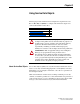
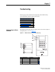
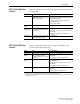
Using the HIM to View Adapter Diagnostic Items
Step Example Screen
1. Access parameters in the adapter. Refer to Using the PowerFlex
7-Class HIM on page 3-2.
2. Press the or key to scroll to Diagnostics.
3. Press the (Enter) key to display the Diagnostics menu in the
adapter.
4. Repeat steps 2 and 3 to enter the Device Items option.
5. Press the or key to scroll through the items.
Main Menu:
Diagnostics
Parameter
Device Select
Device Item # 3
Reference
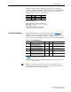
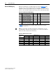
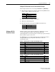
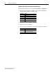
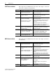
Table 7.A Adapter Diagnostic Items
No. Name Description
1 Common Logic Cmd The present value of the Common Logic Command being transmitted to the drive by this adapter.
2 Product Logic Cmd The present value of the Product Logic Command being transmitted to the drive by this adapter.
3 Reference The present value of the Reference being transmitted to the drive by this adapter. If the drive indicates a 16-bit
Reference size, the Reference value appears in the least significant 16 bits of this diagnostic item, and the most
significant 16 bits of this diagnostic item are zero (0).
4 Common Logic Sts The present value of the Common Logic Status being received from the drive by this adapter.
5 Product Logic Sts The present value of the Product Logic Status being received from the drive by this adapter.
6 Feedback The present value of the Feedback being received from the drive by this adapter. If the drive indicates a 16-bit
Feedback size, the Feedback value appears in the least significant 16 bits of this diagnostic item, and the most
significant 16 bits of this diagnostic item are zero (0).
7 Datalink A1 In The present value of respective Datalink In being transmitted to the drive by this adapter. If not using a Datalink,
this parameter should have a value of zero. If the drive indicates a 16-bit Datalink size, the Datalink value
appears in the least significant 16 bits of this diagnostic item, and the most significant 16 bits of this diagnostic
item are zero (0).
8 Datalink A2 In
9 Datalink B1 In
10 Datalink B2 In
11 Datalink C1 In
12 Datalink C2 In
13 Datalink D1 In
14 Datalink D2 In
15 Datalink A1 Out The present value of respective Datalink Out being received from the drive by this adapter. If the drive indicates
a 16-bit datalink size, the value appears in the least significant 16 bits of this diagnostic item, and the most
significant 16 bits of this diagnostic item are zero (0).
16 Datalink A2 Out
17 Datalink B1 Out
18 Datalink B2 Out
19 Datalink C1 Out
20 Datalink C2 Out
21 Datalink D1 Out
22 Datalink D2 Out
23 Field Flash Cnt Number of times the adapter has been flash updated. (This value is set to zero before the adapter is shipped.)
24 DPI Rx Errors The present value of the DPI CAN Receive error counter.
25 DPI Tx Errors The present value of the DPI CAN Transmit error counter.
26 COPN Rx Errors The present value of the COPN CAN Receive error counter.
27 COPN Tx Errors The present value of the COPN CAN Transmit error counter.