
Manual

Using I/O Messaging 5-9
20-COMM-K CANopen Adapter User Manual
Publication 20COMM-UM012B-EN-P
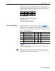
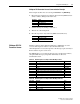
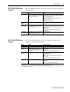
Regardless of the Datalink combination, Datalink x1 Out will always
contain the LSW and Datalink x2 Out will always contain the MSW. In the
following example, the PowerFlex 70 drive Parameter 242 - [Power Up
Marker] contains a value of 88.4541 hours.
Conversion Example:
Parameter 242 - [Power Up Marker] = 88.4541 hours
MSW = 000D
hex
= 1101
binary
= 2
19
+ 2
18
+ 2
16
= 851968
LSW = 7F3D
hex
= 32573
Engineering Value = 851968 + 32573 = 884541
Parameter 242 Displayed Value = 88.4541 Hrs
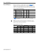
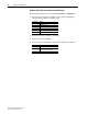
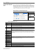
Transmit PDO Mapping
The Transmit PDOs have a default mapping as shown in Table 5.F. The
mapping can be changed if desired. Since every PDO can contain up to
eight bytes of data, it is possible to map, for example, Datalink A1, A2, C1,
and C2 to the same PDO number when using a drive with 16-bit Datalinks.
Table 5.F Default TPDO Mapping
Important:For a 32-bit drive, PDO mapping must be changed from their
default values.
Datalink Word Parameter Data (Hex)
A2 Out MSW 242 000D
B1 Out LSW 242 7F3D
TPDO# Default Mapping Enabled Remap Initial Transmission Type
(1)
(1)
Table 5.H shows the transmission types for the PDO.
1 Product Logic Status (0x2201)
+Feedback 16-bit (0x2204)
Yes No 254 (Asynchronous, COS)
2 Datalink A1 Out 16-bit (0x2216)
+Datalink A2 Out 16-bit (0x2218)
No Yes 253 (Asynchronous, RTR)
3 Datalink B1 Out 16-bit (0x221A)
+Datalink B2 Out 16-bit (0x221C)
No Yes 253 (Asynchronous, RTR)
4 Datalink C1 Out 16-bit (0x221E)
+Datalink C2 Out 16-bit (0x2220)
No Yes 253 (Asynchronous, RTR)
5 Datalink D1 Out 16-bit (0x2222)
+Datalink D2 Out 16-bit (0x2224)
No Yes 253 (Asynchronous, RTR)
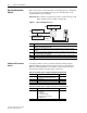
TIP: If a 32-bit drive parameter is mapped to a Datalink pair, it is not
recommended to map part of the pair (that is, A1 or A2) to two different
PDOs since this can give data inconsistency.