
Manual

Installing the Adapter 2-7
20-COMM-K CANopen Adapter User Manual
Publication 20COMM-UM012B-EN-P
Connecting the Adapter to
the Network
1. Remove power from the network and drive.
2. Use static control precautions.
3. Connect one end of a CANopen cable to the network. A CANopen
cable with an outside diameter of 6.9 mm (0.27 in.) is recommended.
Important:Maximum cable length depends on the data rate. For
details, refer to Data Rate
in the Glossary.
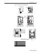
4. Route the other end of the CANopen cable through the bottom of the
PowerFlex drive (Figure 2.4
) and connect a 9-pin D-Sub plug to the
CANopen cable. See Figure 2.5
and its related table for wiring
connection details.
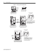
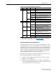
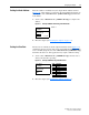
Figure 2.5 Connecting 9-Pin D-Sub Plug to CANopen Cable
5. Connect a 120 Ohm bus termination resistor at both ends of the
CAN-bus cable (at the first and last node, if several adapters are
connected to the CAN-bus). The termination should be made in the
connectors and is not included on the adapter. (See Figure 2.5
.)
6. Connect the CANopen cable plug to the mating adapter receptacle, and
secure it with the two screws.
!
ATTENTION: Risk of injury or death exists. The PowerFlex
drive may contain high voltages that can cause injury or death.
Remove power from the drive, and then verify power has been
discharged before installing or removing the adapter.
Pin Name Function
2 CAN_L CAN low bus line
3 CAN_GND CAN ground
5 CAN_SHLD CAN shield
6 GND Ground (not used)
7 CAN_H CAN high bus line
CAN_H
CAN_L
CAN_GND
CAN_SHLD
7
2
3
5
120 Ohm
Terminating
Resistor