20COMM-UM007A-EN-P.book Page 1 Tuesday, January 22, 2002 10:52 AM Interbus Adapter 20-COMM-I FRN 1.
0COMM-UM007A-EN-P.book Page i Tuesday, January 22, 2002 10:52 AM Table of Contents Table of Contents Preface About This Manual Related Documentation . . . . . . . . . . . . . . . . . . . . . . . . . . . . . P-1 Conventions Used in this Manual . . . . . . . . . . . . . . . . . . . . . P-2 Rockwell Automation Support. . . . . . . . . . . . . . . . . . . . . . . . P-2 Summary of Changes . . . . . . . . . . . . . . . . . . . . . . . . . . . . . . . P-4 Chapter 1 Getting Started Components . . . . . . . . .
20COMM-UM007A-EN-P.book Page ii Tuesday, January 22, 2002 10:52 AM ii Table of Contents Chapter 5 Using I/O Messaging About I/O Messaging . . . . . . . . . . . . . . . . . . . . . . . . . . . . . . . 5-1 Understanding the I/O Image. . . . . . . . . . . . . . . . . . . . . . . . . 5-2 Using Logic Command/Status . . . . . . . . . . . . . . . . . . . . . . . . 5-4 Using Reference/Feedback . . . . . . . . . . . . . . . . . . . . . . . . . . 5-4 Using Datalinks . . . . . . . . . . . . . . . . . . . . . . . .
20COMM-UM007A-EN-P.book Page 2 Tuesday, January 22, 2002 10:52 AM Important User Information Solid state equipment has operational characteristics differing from those of electromechanical equipment. “Safety Guidelines for the Application, Installation and Maintenance of Solid State Controls” (Publication SGI-1.1) describes some important differences between solid state equipment and hard-wired electromechanical devices.
20COMM-UM007A-EN-P.book Page 1 Tuesday, January 22, 2002 10:52 AM Preface About This Manual Topic Related Documentation Conventions Used in this Manual Rockwell Automation Support Summary of Changes Page P-1 P-2 P-2 P-4 Related Documentation For: DriveExplorer™ DriveExecutive HIM PowerFlex™ 70 Drive PowerFlex 700 Drive Scanner SLC SLC Interbus Refer to: DriveExplorer Getting Results Manual Online Help (installed with the software) www.ab.
20COMM-UM007A-EN-P.book Page 2 Tuesday, January 22, 2002 10:52 AM P-2 About This Manual Conventions Used in this Manual The following conventions are used throughout this manual: • • • • Parameter names are shown in the following format Parameter xxx - [*]. The xxx represents the parameter number. The * represents the parameter name. For example Parameter 01 - [DPI Port]. Menu commands are shown in bold type face and follow the format Menu > Command.
20COMM-UM007A-EN-P.book Page 3 Tuesday, January 22, 2002 10:52 AM About This Manual U.S. Allen-Bradley Drives Technical Support: E-mail: support@drives.ra.rockwell.com Tel: (1) 262.512.8176 Fax: (1) 262.512.2222 Online: www.ab.com/support/abdrives UK Customer Support Center: E-mail: esupport2@ra.rockwell.com Tel: +44 (0) 870 2411802 Fax: +44 (0) 1908 838804 German Customer Service Center: E-mail: ragermany-csc@ra.rockwell.
20COMM-UM007A-EN-P.book Page 4 Tuesday, January 22, 2002 10:52 AM P-4 About This Manual Summary of Changes This is the first release of the 20-COMM-I manual.
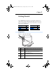
20COMM-UM007A-EN-P.book Page 1 Tuesday, January 22, 2002 10:52 AM Chapter 1 Getting Started The 20-COMM-I Interbus adapter is an embedded communication option for any one drive in the PowerFlex family. It can also be used with other Allen-Bradley products implementing DPI™, a functional enhancement to SCANport™. Topic Components Features Compatible Products Required Equipment Page 1-1 1-2 1-2 1-3 Topic Safety Precautions Quick Start Modes of Operation Page 1-4 1-5 1-6 Components Figure 1.
20COMM-UM007A-EN-P.book Page 2 Tuesday, January 22, 2002 10:52 AM 1-2 Getting Started Features The Interbus adapter features the following: • • • • • • The adapter is mounted in the PowerFlex drive and receives the required power from the drive. Captive screws are used to secure the adapter to the drive. A number of configuration tools can be used to configure the adapter and connected drive.
20COMM-UM007A-EN-P.book Page 3 Tuesday, January 22, 2002 10:52 AM Getting Started Required Equipment Equipment Shipped with the Adapter When you unpack the adapter, verify that the package includes: ❑ ❑ ❑ ❑ ❑ One Interbus adapter A 2.54 cm (1 in.) and a 15.24 cm (6 in.
20COMM-UM007A-EN-P.book Page 4 Tuesday, January 22, 2002 10:52 AM Getting Started 1-4 Safety Precautions Please read the following safety precautions carefully. ! ! ! ! ! ! ATTENTION: Risk of injury or equipment damage exists. Only personnel familiar with drive and power products and the associated machinery should plan or implement the installation, start-up, configuration, and subsequent maintenance of the product using a Interbus adapter.
20COMM-UM007A-EN-P.book Page 5 Tuesday, January 22, 2002 10:52 AM Getting Started 1-5 Quick Start This section is designed to help experienced users start using the Interbus adapter. If you are unsure about how to complete a step, refer to the referenced chapter. Step 1 Review the safety precautions for the adapter. 2 3 4 5 6 7 8 Refer to Throughout This Manual Verify that the PowerFlex drive is properly Drive User installed. Manual Install the adapter.
20COMM-UM007A-EN-P.book Page 6 Tuesday, January 22, 2002 10:52 AM 1-6 Getting Started Modes of Operation The adapter uses five status indicators to report its operating status. They can be viewed on the adapter or through the drive cover. (See Figure 1.2.) Figure 1.2 Status Indicators ➊ ➋ ➌ ➍ PWR STS ➎ CC RD TR BA ➊ ➋ ➌ ➍ # Status Indicator ➊ CC Cable Check ➋ RD Remote Bus Disable ➌ TR Transmit/Receive Normal Description Status(1) Green Cable connections good.
20COMM-UM007A-EN-P.
20COMM-UM007A-EN-P.
20COMM-UM007A-EN-P.book Page 1 Tuesday, January 22, 2002 10:52 AM Chapter 2 Installing the Adapter Chapter 2 provides instructions for installing the adapter on a PowerFlex drive. Topic Preparing for an Installation Connecting the Adapter to the Network Connecting the Adapter to the Drive Applying Power Page 2-1 2-2 2-4 2-6 Preparing for an Installation Before installing the Interbus adapter: • ! Verify that you have all required equipment. Refer to Chapter 1, Getting Started.
20COMM-UM007A-EN-P.book Page 2 Tuesday, January 22, 2002 10:52 AM 2-2 Installing the Adapter Connecting the Adapter to the Network ! ATTENTION: Risk of injury or death exists. The PowerFlex drive may contain high voltages that can cause injury or death. Remove power from the drive, and then verify power has been discharged before installing or removing an adapter. 1. Remove power from the drive. 2. Use static control precautions. 3. Route the Interbus cables through the bottom of the PowerFlex drive.
20COMM-UM007A-EN-P.book Page 3 Tuesday, January 22, 2002 10:52 AM Installing the Adapter 2-3 Figure 2.1 Example Network Wiring SST SLC Scanner DO DI COM 1 2 3 4 /DO /DI 6 7 5 8 Station 1 1 9 9-pin D-shell jumper Shield Bus Out 2 3 /DO1 DO1 /DI1 4 DI1 Bus In 5 6 /DO2 DO2 /DI2 DI2 GND RBST PE 1 2 3 4 5 6 7 GND PE jumper /DO2 Station 2 1 2 /DO1 DO1 3 4 5 6 /DI1 DI1 GND PE 1 Bus Out DO2 /DI2 2 Bus In 5. Connect the Interbus connector to the adapter.
COMM-UM007A-EN-P.book Page 4 Tuesday, January 22, 2002 10:52 AM 2-4 Installing the Adapter Connecting the Adapter to the Drive 1. Remove power from the drive. 2. Use static control precautions. 3. Connect the Internal Interface cable to the DPI port on the drive and then to DPI connector on the adapter. Figure 2.2 DPI Ports and Internal Interface Cables ➊ ➋ Interbus Adapter ➌ ➍ PowerFlex 70 Drive PowerFlex 700 Drive 2 Frame & Larger PowerFlex 700 Drive 0 - 1 Frame # ➊ ➋ Description 15.
20COMM-UM007A-EN-P.book Page 5 Tuesday, January 22, 2002 10:52 AM Installing the Adapter 4. Fold the Internal Interface cable behind the adapter and mount the adapter on the drive using the four captive screws to secure and ground it to the drive. Important: On a PowerFlex 70 drive, tighten the screw in the lower right hole to ground the adapter. On a PowerFlex 700 drive, tighten the screw in the lower left hole to ground the adapter. Figure 2.
20COMM-UM007A-EN-P.book Page 6 Tuesday, January 22, 2002 10:52 AM 2-6 Installing the Adapter Applying Power ! ATTENTION: Risk of equipment damage, injury, or death exists. Unpredictable operation may occur if you fail to verify that parameter settings and switch settings are compatible with your application. Verify that settings are compatible with your application before applying power to the drive. 1. Close the door or reinstall the cover on the drive.
20COMM-UM007A-EN-P.book Page 1 Tuesday, January 22, 2002 10:52 AM Chapter 3 Configuring the Adapter Chapter 3 provides instructions and information for setting the parameters in the adapter. Topic Configuration Tools Using the PowerFlex HIM Setting the I/O Configuration Page 3-1 3-2 3-3 Topic Setting a Fault Action Resetting the Adapter Page 3-6 3-7 For a list of parameters, refer to Adapter Parameters. For definitions of terms in this chapter, refer to the Glossary.
20COMM-UM007A-EN-P.book Page 2 Tuesday, January 22, 2002 10:52 AM 3-2 Configuring the Adapter Using the PowerFlex HIM If your drive has either an LED or LCD HIM (Human Interface Module), access parameters in the adapter as follows: Using an LED HIM Step 1. Press the ALT and then Sel (Device) to display the Device Screen. 2. Press the Up Arrow or Down Arrow to scroll to the Interbus adapter. Letters represent files in the drive, and numbers represent ports. The adapter is usually connected to port 5. 3.
20COMM-UM007A-EN-P.book Page 3 Tuesday, January 22, 2002 10:52 AM Configuring the Adapter 3-3 Setting the I/O Configuration The I/O configuration determines the data that is sent to and from the drive. This is a two part process: enabling/disabling the data transmitted between the adapter and drive, and identifying the data transmitted between the adapter and the scanner. 1. Enable or disable the data transmitted between the adapter and drive.
20COMM-UM007A-EN-P.book Page 4 Tuesday, January 22, 2002 10:52 AM 3-4 Configuring the Adapter 4. Interbus requires the network I/O mapping to be configured first in the adapter. CMD software will read this configuration online when it is configuring the scanner. Process Input Data Description (PIDD) words map input data on the network (data seen as inputs to the scanner and controller program). Example input data includes Logic Status, Feedback and Datalinks (Datalink x1 Out).
20COMM-UM007A-EN-P.
20COMM-UM007A-EN-P.book Page 6 Tuesday, January 22, 2002 10:52 AM 3-6 Configuring the Adapter Setting a Fault Action By default, when communications are disrupted (for example, a cable is disconnected) the drive responds by faulting if it is using I/O from the network. You can configure a different response to communication disruptions using Parameter 6 - [Comm Flt Action]. ! ATTENTION: Risk of injury or equipment damage exists.
20COMM-UM007A-EN-P.book Page 7 Tuesday, January 22, 2002 10:52 AM Configuring the Adapter 3-7 To set the fault configuration parameters If you set Parameter 6 - [Comm Flt Action] to the “Send Flt Cfg,” the values in the following parameters are sent to the drive after a communications fault occurs. You must set these parameters to values required by your application. Number 10 11 12 – 19 Name Flt Cfg Logic Flt Cfg Ref Flt Cfg x1 In Description A 16-bit value sent to the drive for Logic Command.
20COMM-UM007A-EN-P.book Page 8 Tuesday, January 22, 2002 10:52 AM 3-8 Configuring the Adapter The following parameters provide information about how the adapter is configured. You can view these parameters at any time. Parameter No. Name and Description 01 [DPI Port] Port to which the adapter is connected. This will usually be port 5. 03 04 09 21 23 25 27 29 31 [Ref/Fdbk Size] Size of the Reference/Feedback. The drive determines the size of the Reference/Feedback.
20COMM-UM007A-EN-P.book Page 9 Tuesday, January 22, 2002 10:52 AM Configuring the Adapter Parameter No. Name and Description 33 PIDD W6 Actual Actual Process Input Description for Word 6 Displays the Actual PIDD Config being transmitted to word 6 in the Interbus Master. 35 PIDD W7 Actual Actual Process Input Description for Word 7 Displays the Actual PIDD Config being transmitted to word 7 in the Interbus Master.
20COMM-UM007A-EN-P.
20COMM-UM007A-EN-P.book Page 1 Tuesday, January 22, 2002 10:52 AM Chapter 4 Configuring the Interbus Scanner Interbus scanners are available from several manufacturers, including SST. Chapter 4 provides instructions on how to utilize Phoenix Contact CMD software to configure the network on an SST scanner.
20COMM-UM007A-EN-P.book Page 2 Tuesday, January 22, 2002 10:52 AM 4-2 Configuring the Interbus Scanner Figure 4.1 Example Interbus Network Fault LED COMM LED Interbus REMOTE OUT Config RS232 Port PowerFlex 70 Station 1.0 (CR=2) PowerFlex 70 Station 2.
20COMM-UM007A-EN-P.
20COMM-UM007A-EN-P.book Page 4 Tuesday, January 22, 2002 10:52 AM 4-4 Configuring the Interbus Scanner Using CMD Software to Configure the Network Before starting the configuration, make sure the PC running CMD software is connected to the SST scanner (a null modem cable is supplied with the scanner). The SLC and drives need to be connected to the Interbus network and powered in order for CMD to configure the network.
20COMM-UM007A-EN-P.book Page 5 Tuesday, January 22, 2002 10:52 AM Configuring the Interbus Scanner 4-5 Figure 4.3 Entering a name for the new Interbus project 3. Right-click on the PLC/PC icon and select Description. Enter a name for the controller and any additional information desired, as shown in Figure 4.4. Click OK when complete. Figure 4.4 Entering a name for the Interbus controller 4. Right-click on the Program icon and select Description.
20COMM-UM007A-EN-P.book Page 6 Tuesday, January 22, 2002 10:52 AM 4-6 Configuring the Interbus Scanner 5. When complete, the representation area will look as shown in Figure 4.6. Figure 4.6 Example Interbus CMD Project This provides useful information regarding the CMD project being created: • “PowerFlex 70 Interbus Demo” indicates what this project is for. • “SLC 5/05” indicates the controller used. • “Interbus_SLC_Demo” indicates that Interbus_SLC_Demo.
20COMM-UM007A-EN-P.book Page 7 Tuesday, January 22, 2002 10:52 AM Configuring the Interbus Scanner 4-7 9. Right-click on the Controller Board icon and select Type. Set the type to “IBS USC/4(4K)” and click OK. This identifies the type of Interbus controller used on the SST scanner. (See Figure 4.8.) Figure 4.8 Selecting the Interbus Controller type 10. Right-click on the Controller Board icon and select Description. Enter “SST-IBS-SLC” in the name field, as shown in Figure 4.9. Figure 4.
20COMM-UM007A-EN-P.book Page 8 Tuesday, January 22, 2002 10:52 AM 4-8 Configuring the Interbus Scanner 11. When complete, the representation area will look as shown in Figure 4.10. Figure 4.10 Example Interbus CMD Project 12. From the pull-down menu select Configuration/Configuration Frame/Read In and answer Yes to changing the operating state to Configuration Online. If there are additional prompts, answer OK or Yes to perform the read anyway. CMD will then read the bus configuration. (See Figure 4.11.
20COMM-UM007A-EN-P.book Page 9 Tuesday, January 22, 2002 10:52 AM Configuring the Interbus Scanner 4-9 The gray PCP icons represent each PowerFlex 70 drive. The first PowerFlex 70 has a Device Number of 1.0 and the second has a Device Number of 2.0. 13. Right-click on the SST-IBS-SLC scanner and select Process Data. This shows the Interbus I/O mapping for each device on the network, as shown in Figure 4.12. Figure 4.
20COMM-UM007A-EN-P.book Page 10 Tuesday, January 22, 2002 10:52 AM 4-10 Configuring the Interbus Scanner The scanner mapping correlates to SLC addressing as follows: Scanner (USC/4) SLC Scanner (USC/4) 0 1 O:x.0(high) O:x.0(low) 512 513 63 64 65 O:x.31(low) M0:x.0(high) M0:x.0(low) 575 576 511 M0:x.223(low) 1023 Output Input SLC I:x.0(high) I:x.0(low) I:x.31(low) M1:x.0(high) M1:x.0(low) M1:x.223(low) The mapping in the scanner is set up in bytes.
20COMM-UM007A-EN-P.book Page 11 Tuesday, January 22, 2002 10:52 AM Configuring the Interbus Scanner 4-11 Using the PIDD/PODD values previously set in the 20-COMM-I, the I/O layout in the scanner is as follows: Word Inputs (Data to Master) 0 1 2 3 4 5 6 7 8 Logic Status Feedback Datalink A1 Out Datalink A2 Out Datalink B1 Out Datalink B2 Out Datalink C1 Out Datalink C2 Out Datalink D1 Out Station 1.0 2.
20COMM-UM007A-EN-P.book Page 12 Tuesday, January 22, 2002 10:52 AM 4-12 Configuring the Interbus Scanner Figure 4.13 Entering a Station Name 15. Click on the Parameter Channel button. Set the Transmit and Receive to 128 bytes and enable Read, Write, and Get-0D (long format) services, as shown in Figure 4.14. Click OK when complete. Figure 4.
20COMM-UM007A-EN-P.book Page 13 Tuesday, January 22, 2002 10:52 AM Configuring the Interbus Scanner 16. Repeat steps #14 and #15 using the 2.0 PCP icon 4-13 . Enter a Station name such as “PowerFlex 70 Demo #2”. Note the Communication Reference (CR) is 3. The CR needs to be known when using PCP communication services (explicit messaging). Click OK when complete. 17. When complete, the representation area will look as shown in Figure 4.15. Figure 4.15 Example PowerFlex 70 Demo #2 18.
20COMM-UM007A-EN-P.book Page 14 Tuesday, January 22, 2002 10:52 AM 4-14 Configuring the Interbus Scanner Figure 4.16 Selecting data for Parameterization/Execute screen If parameterization execution is successful, there will be a prompt to click OK. Click OK. 19. When complete, the representation area will look as shown in Figure 4.17. Figure 4.17 Example Parameterization Execution 20. Click File/Save from the pull-down menu and save the project.
20COMM-UM007A-EN-P.book Page 15 Tuesday, January 22, 2002 10:52 AM Configuring the Interbus Scanner 4-15 PowerFlex 70 Settings to use with Ladder Examples The following parameters should be configured to use the example ladder logic program.
20COMM-UM007A-EN-P.book Page 16 Tuesday, January 22, 2002 10:52 AM 4-16 Configuring the Interbus Scanner Figure 4.18 Scanner I/O Configuration Figure 4.
20COMM-UM007A-EN-P.
20COMM-UM007A-EN-P.
20COMM-UM007A-EN-P.book Page 1 Tuesday, January 22, 2002 10:52 AM Chapter 5 Using I/O Messaging Chapter 5 provides information and examples that explain how to use I/O Messaging to control a PowerFlex drive.
20COMM-UM007A-EN-P.book Page 2 Tuesday, January 22, 2002 10:52 AM 5-2 Using I/O Messaging Understanding the I/O Image The terms input and output are defined from scanner’s point of view. Therefore, Output I/O is data that is output from the scanner and consumed by the Interbus adapter. Input I/O is status data that is produced by the adapter and consumed as input by the scanner.
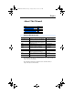
20COMM-UM007A-EN-P.book Page 3 Tuesday, January 22, 2002 10:52 AM Using I/O Messaging 5-3 An image that uses 32-bit words for Reference and Datalinks would change the I/O image as follows: Word 0 1-2 3-6 7 - 10 I/O Logic Command/Status Reference/Feedback Datalink A1/A2 Datalink B1/B2 Figure 5.2 illustrates an example of an I/O image that does not use all of the I/O data. Only the Logic Command/Reference and Datalink B are enabled.
20COMM-UM007A-EN-P.book Page 4 Tuesday, January 22, 2002 10:52 AM 5-4 Using I/O Messaging Using Logic Command/Status When enabled, the Logic Command/Status word is always word 0 in the I/O image. The Logic Command is a 16-bit word of control produced by the scanner and consumed by the adapter. The Logic Status is a 16-bit word of status produced by the adapter and consumed by the scanner.
20COMM-UM007A-EN-P.book Page 5 Tuesday, January 22, 2002 10:52 AM Using I/O Messaging 5-5 32-Bit Parameters using 16-Bit Datalinks To read (and/or write) a 32-bit parameter using 16-bit Datalinks, typically both Datalinks (x1 and x2) are set to the 32-bit parameter. For example, to read Parameter 09 - [Elapsed MWh] in a PowerFlex 70, both Datalink A1 and A2 are set to “9”. Datalink A1 will contain the least significant word (LSW) and Datalink A2 the most significant word (MSW).
20COMM-UM007A-EN-P.book Page 6 Tuesday, January 22, 2002 10:52 AM 5-6 Using I/O Messaging SLC Example Ladder Logic Program The Interbus example program uses a SLC processor with an SST Interbus scanner (SST-IBS-SLC) in the first slot of the rack and will work with PowerFlex 70 or PowerFlex 700 drives.
20COMM-UM007A-EN-P.book Page 7 Tuesday, January 22, 2002 10:52 AM Using I/O Messaging 5-7 SLC Data Table Read Data The scanner is configured for 18 bytes (9 words) of inputs for each drive, the maximum amount allowed. Two drives require 36 bytes (18 words) max. Station 1 Address I:1.0 I:1.1 I:1.2 I:1.3 I:1.4 I:1.5 I:1.6 I:1.7 I:1.8 Station 2 Address I:1.9 I:1.10 I:1.11 I:1.12 I:1.13 I:1.14 I:1.15 I:1.16 I:1.
20COMM-UM007A-EN-P.book Page 8 Tuesday, January 22, 2002 10:52 AM 5-8 Using I/O Messaging SLC Ladder Logic Example - Main Program Figure 5.3 Example SLC Ladder Logic - Main Program The following rung performs power-up initialization of the PCP Read and PCP Write routines.
20COMM-UM007A-EN-P.book Page 9 Tuesday, January 22, 2002 10:52 AM Using I/O Messaging 5-9 SLC Ladder Logic Example - Station 1 Program Figure 5.4 Example SLC Ladder Logic - Station 1 Program Controlling the Logic Command to the drive at Station 1.0. Station 1.0 Start Command B3:20 Station 1.0 Logic Command START O:1.0 0000 1 1 OTHER Station 1.0 Stop Command B3:20 Station 1.0 Logic Command STOP O:1.0 0 0 OTHER Station 1.0 Jog Command B3:20 Station 1.0 Logic Command JOG O:1.
20COMM-UM007A-EN-P.book Page 10 Tuesday, January 22, 2002 10:52 AM 5-10 Using I/O Messaging Figure 5.4 Example SLC Ladder Logic - Station 1 Program (Continued) Station 1.0 Datalink A2 Datalink A2 (Pr. 301) set to Deceleration Time 1 (Pr. 142) Station 1.0 Datalink A2 MOV Move Source 0008 Dest N19:3 50< O:1.3 50< Station 1.0 Datalink B1 Datalink B1 (Pr. 302) set to Jog Speed (Pr. 100) Station 1.0 Datalink B1 MOV Move Source 0009 Dest N19:4 100< O:1.4 100< Station 1.0 Datalink B2 Datalink B2 (Pr.
20COMM-UM007A-EN-P.book Page 11 Tuesday, January 22, 2002 10:52 AM Using I/O Messaging SLC Ladder Logic Example - Station 2 Program Figure 5.5 Example SLC Ladder Logic - Station 2 Program Controlling the Logic Command to the drive at Station 2.0. Station 2.0 Start Command B3:21 Station 2.0 Logic Command START O:1.9 0000 1 1 OTHER Station 2.0 Stop Command B3:21 Station 2.0 Logic Command STOP O:1.9 0 0 OTHER Station 2.0 Jog Command B3:21 Station 2.0 Logic Command JOG O:1.
20COMM-UM007A-EN-P.book Page 12 Tuesday, January 22, 2002 10:52 AM 5-12 Using I/O Messaging Figure 5.5 Example SLC Ladder Logic - Station 2 Program (Continued) Station 2.0 Datalink A2 Datalink A2 (Pr. 301) set to Deceleration Time 1 (Pr. 142) Station 2.0 Datalink A2 MOV Move Source 0008 Dest N19:17 50< O:1.12 50< Station 2.0 Datalink B1 Datalink B1 (Pr. 302) set to Jog Speed (Pr. 100) Station 2.0 Datalink B1 MOV Move Source 0009 Dest N19:18 100< O:1.13 100< Station 2.0 Datalink B2 Datalink B2 (Pr.
20COMM-UM007A-EN-P.book Page 1 Tuesday, January 22, 2002 10:52 AM Chapter 6 Using Explicit Messaging (PCP Communications) Chapter 6 provides information and examples that explain how to use Explicit Messaging to monitor and configure the adapter and connected PowerFlex drive, as well as other peripherals.
20COMM-UM007A-EN-P.book Page 2 Tuesday, January 22, 2002 10:52 AM 6-2 Using Explicit Messaging (PCP Communications) Running Explicit Messages There are five basic events in the Explicit Messaging process defined below. The details of each step will vary depending on the controller. Refer to the documentation for your controller. Important: There must be a request message and a response message for all Explicit Messages, whether you are reading or writing data. Figure 6.
20COMM-UM007A-EN-P.book Page 3 Tuesday, January 22, 2002 10:52 AM Using Explicit Messaging (PCP Communications) 6-3 PCP Communications Peripheral Communications Protocol (PCP) messages are used for explicit messaging, which is not part of the normal Interbus I/O data scan. The scanner takes care of all of the details of establishing a connection for PCP communication services. PCP communications can be used to: • Read or write DPI Host (PowerFlex 70, etc.
20COMM-UM007A-EN-P.book Page 4 Tuesday, January 22, 2002 10:52 AM 6-4 Using Explicit Messaging (PCP Communications) Figure 6.
20COMM-UM007A-EN-P.book Page 5 Tuesday, January 22, 2002 10:52 AM Using Explicit Messaging (PCP Communications) 6-5 The ladder example used in this manual performs PCP Reads and PCP Writes.
20COMM-UM007A-EN-P.book Page 6 Tuesday, January 22, 2002 10:52 AM 6-6 Using Explicit Messaging (PCP Communications) The example ladder logic program simplifies addressing the various PCP indexes. Before calling the PCP Read Subroutine (Figure 6.3), three registers are loaded to identify the variable to be read: Table 6.2 PCP Read Main Program Data N22:0 N22:1 N22:2 The Communication Reference (CR) to read from: Set to “2” to access Station 1.0 (CR=2) Set to “3” to access Station 2.
20COMM-UM007A-EN-P.book Page 7 Tuesday, January 22, 2002 10:52 AM Using Explicit Messaging (PCP Communications) 6-7 Command N22:10 4 4 N22:11 2 2 Reply ptio n Des cr i (He x) c) Valu e (De Valu e Mes sag e SLC Add ress Read Examples Reading Pr. 140 [Accel Time 1] from a PowerFlex 70 (DPI Host) Command word = 4 = PCP Read (bit 2 ON) CR# = 2 (Station 1.0) N22:12 12428 308C Index =3000h+8Ch = Parameter 140 [Accel Time] 3001h is the start of PowerFlex 70 parameters (Pr.
20COMM-UM007A-EN-P.book Page 8 Tuesday, January 22, 2002 10:52 AM Using Explicit Messaging (PCP Communications) Des crip tion (He x) Valu e (De c) ress Valu e Add SLC Mes sag e Reading Pr. 244 [Fault 1 Time] from a PowerFlex 70 (DPI Host) Command N22:10 4 4 Command word = 4 = PCP Read (bit 2 ON) N22:11 2 2 CR# = 2 (Station 1.0) N22:12 12532 Reply 30F4 Index =3000h+F4h = Parameter 244 [Fault 1 Time] 3001h is the start of PowerFlex 70 parameters (Pr.
20COMM-UM007A-EN-P.book Page 9 Tuesday, January 22, 2002 10:52 AM Using Explicit Messaging (PCP Communications) 6-9 tion Des crip ex) Valu e (H ec) ss Valu e (D SLC Add re Mes sag e Reading Pr. 21 [PIDD W0 Actual] from a 20-COMM-I Command N22:10 4 4 Command word = 4 = PCP Read (bit 2 ON) N22:11 2 2 CR# = 2 (Station 1.0) Index =2FB5h+15h = Parameter 21 [PIDD W0 Actual] N22:12 12234 2FCA 2FB6h is the start of the 20-COMM-I parameters (Pr.
20COMM-UM007A-EN-P.
20COMM-UM007A-EN-P.book Page 11 Tuesday, January 22, 2002 10:52 AM Using Explicit Messaging (PCP Communications) 6-11 The example ladder logic program simplifies addressing the various PCP indexes. Before calling the PCP Write Subroutine (Figure 6.4), six registers are loaded to identify the variable to write: Table 6.5 PCP Write Main Program Data N23:0 N23:1 N23:2 N23:3 N23:4 N23:5 The Communication Reference (CR) to write to: Set to “2” to access Station 1.0 (CR=2) Set to “3” to access Station 2.
20COMM-UM007A-EN-P.book Page 12 Tuesday, January 22, 2002 10:52 AM Using Explicit Messaging (PCP Communications) on Des c ripti (He x) Valu e Valu e (De c) SLC Add ress Mes sag e Write Examples: Writing Pr. 106 [Preset Speed 6] to a PowerFlex 70 (DPI Host) Command N23:10 8 8 Command word = 8 = PCP Write (bit 3 ON) N23:11 2 2 CR# = 2 (Station 1.0) Index = 3000h+6Ah = Parameter 106 [Preset Speed 6] 3001h is the start of PowerFlex 70 parameters (Pr.
20COMM-UM007A-EN-P.book Page 13 Tuesday, January 22, 2002 10:52 AM Using Explicit Messaging (PCP Communications) 6-13 ptio n Des cr i ( He x) Valu e ( De c) ress Valu e Add SLC Mes sag e Writing Pr. 6 [Comm Flt Action] to a 20-COMM-I Command N23:10 8 8 Command word = 8 = PCP Write (bit 3 ON) N23:11 2 2 CR# = 2 (Station 1.0) N23:12 12219 2FBB Reply Index = 2FB5h+6h = Parameter 6 [Comm Flt Action 2FB6h is the start of the 20-COMM-I parameters (Pr.
20COMM-UM007A-EN-P.book Page 14 Tuesday, January 22, 2002 10:52 AM Using Explicit Messaging (PCP Communications) ripti on ex) Des c Valu e (H ec) Valu e (D SLC Mes sag e Add ress Writing Pr. 12 [Flt Cfg A1] to a 20-COMM-I Command N23:10 8 8 Command word = 8 = PCP Write (bit 3 ON) N23:11 2 2 CR# = 2 (Station 1.0) N23:12 12225 2FC1 Index = 2FB5h+Ch = Parameter 12 [Flt Cfg A1 In] 2FB6h is the start of the 20-COMM-I parameters (Pr.
20COMM-UM007A-EN-P.book Page 15 Tuesday, January 22, 2002 10:52 AM Using Explicit Messaging (PCP Communications) 6-15 SLC Ladder Example - Peripheral Communications Protocol (PCP) PCP Read Subroutine (Explicit Messaging) The PCP Read Subroutine is executed from the Main Program (Chapter 5) by turning on bit B3:47/0. Only one PCP Read or Write can be performed at any one time.
20COMM-UM007A-EN-P.book Page 16 Tuesday, January 22, 2002 10:52 AM 6-16 Using Explicit Messaging (PCP Communications) Figure 6.
20COMM-UM007A-EN-P.book Page 17 Tuesday, January 22, 2002 10:52 AM Using Explicit Messaging (PCP Communications) 6-17 Figure 6.3 LAD5 - PCP Read Subroutine (Continued) Copy the PCP Read Command message to the scanner for transmission on the network. PCP Read Routine 1-shot B3:47 0004 1 0005 0006 0007 COP Copy File Source Dest Length #N22:10 #M0:1.
20COMM-UM007A-EN-P.book Page 18 Tuesday, January 22, 2002 10:52 AM 6-18 Using Explicit Messaging (PCP Communications) Figure 6.3 LAD5 - PCP Read Subroutine (Continued) 0010 If the PCP Read Reply message indicates that the result was "not good" (N22:24 <> 0), then zero out the data area of the Reply message (might contain leftover data from a previous successful PCP Read). PCP Read PCP Read Status PCP Read Reply Msg Reply Msg Message Reply Msg Present 1-Shot Result Data Word #1 MOV M1:1.
20COMM-UM007A-EN-P.book Page 19 Tuesday, January 22, 2002 10:52 AM Using Explicit Messaging (PCP Communications) 6-19 PCP Write Subroutine (Explicit Messaging) The PCP Write Subroutine is executed from the Main Program (Chapter 5) by turning on bit B3:47/10. Only one PCP Read or Write can be performed at any one time. B3:47/10 will be turned off by the subroutine when the reading is complete and signals that another read (or write) cycle can take place. Figure 6.
20COMM-UM007A-EN-P.book Page 20 Tuesday, January 22, 2002 10:52 AM 6-20 Using Explicit Messaging (PCP Communications) Figure 6.
20COMM-UM007A-EN-P.book Page 21 Tuesday, January 22, 2002 10:52 AM Using Explicit Messaging (PCP Communications) 6-21 Figure 6.4 LAD6 - PCP Write Subroutine (Continued) Status Message Present M1:1.0 0009 15 0010 PCP Write Reply Msg 1-Shot B3:47 L 12 When the Command / Status Message handshake is complete, reset the 1-shot bits and exit the PCP Write routine by turning the "Execute PCP Write" bit off (B3:47/10) Command Status Execute Message Message PCP Write Acknowledge Present Subroutine M0:1.0 M1:1.
20COMM-UM007A-EN-P.
20COMM-UM007A-EN-P.book Page 1 Tuesday, January 22, 2002 10:52 AM Chapter 7 Troubleshooting Chapter 7 contains troubleshooting information. Topic Locating the Status Indicators Page 7-1 Cable Check (CC) Status 7-2 Indicator Remote Bus Disable (RD) Status 7-2 Indicator Topic Page Transmit/Receive (TR) Status 7-2 Indicator Bus Active (BA) Status Indicator 7-3 Adapter Diagnostic Items 7-4 Viewing and Clearing Events 7-5 Locating the Status Indicators The Interbus adapter has five status indicators.
20COMM-UM007A-EN-P.book Page 2 Tuesday, January 22, 2002 10:52 AM 7-2 Troubleshooting Note: The UL indicator is not viewable when the drive cover is installed or closed. Note: Interbus compliance requires different LED functions than what is normally displayed on the front of the drive (Port, Mod, Net A and Net B Leds). LED labels are provided with the adapter for application to the drive cover.
20COMM-UM007A-EN-P.book Page 3 Tuesday, January 22, 2002 10:52 AM Troubleshooting Bus Active (BA) Status Indicator Status Off Solid Green Flash Green Cause Bus not active. Bus active, exchanging data. Bus active, but no data exchange. Corrective Actions • Set master to start data transmission. • No action. • Set master to start data transmission. Bus Voltage (UL) Status Indicator(1) Status Off Cause Bus voltage is not OK. Solid Green Bus active.
20COMM-UM007A-EN-P.book Page 4 Tuesday, January 22, 2002 10:52 AM 7-4 Troubleshooting Adapter Diagnostic Items Adapter Diagnostic Items are viewable with DriveExplorer (version 2.01 or higher), DriveExecutive (version v1.01 or higher) or LCD HIM (2.001 or higher) software. Diagnostic items show current data being transmitted and received by the Host device (e.g. drive), and other diagnostic information regarding the 20-COMM-I. No.
20COMM-UM007A-EN-P.book Page 5 Tuesday, January 22, 2002 10:52 AM Troubleshooting 7-5 Viewing and Clearing Events The adapter maintains an event queue that reports the history of its actions. You can view the event queue using an LCD PowerFlex HIM, DriveExplorer (2.01 or higher) software, or DriveExecutive (1.01 or higher). Step Keys Viewing Events 1. Access parameters in the adapter. Refer to Using the PowerFlex HIM in Chapter 3. 2. Press the Up Arrow or Down Arrow to scroll to Diagnostics. 3.
20COMM-UM007A-EN-P.book Page 6 Tuesday, January 22, 2002 10:52 AM 7-6 Troubleshooting Events Many events in the Event queue occur under normal operation. If you encounter unexpected communications problems, the events may help you or Allen-Bradley personnel troubleshoot the problem.
20COMM-UM007A-EN-P.book Page 7 Tuesday, January 22, 2002 10:52 AM Troubleshooting Code 25 26 27 Event IB Online IB Offline Lang CRC Bad Description The Interbus adapter has gone on-line the Interbus network. The Interbus adapter has gone off-line the Interbus network.
20COMM-UM007A-EN-P.
20COMM-UM007A-EN-P.book Page 1 Tuesday, January 22, 2002 10:52 AM Appendix A Specifications This chapter presents the specifications for the adapter. Topic Communications Electrical Mechanical Page A-1 A-1 A-1 Topic Page Environmental A-2 Regulatory Compliance A-2 Communications Network Protocol Data Rates Drive Protocol Data Rates Interbus 500K DPI 125K or 500K Electrical Consumption Drive Network 450mA at 5 V supplied through the drive Mechanical Dimensions Height Length Width Weight 19 mm (0.
20COMM-UM007A-EN-P.
20COMM-UM007A-EN-P.book Page 1 Tuesday, January 22, 2002 10:52 AM Appendix B Adapter Parameters Appendix B provides information about the Interbus adapter parameters. Topic Page About Parameter Numbers B-1 Parameters List B-1 About Parameter Numbers The parameters in the adapter are numbered consecutively. However, depending on which configuration tool you use, they may have different numbers.
20COMM-UM007A-EN-P.book Page 2 Tuesday, January 22, 2002 10:52 AM B-2 Adapter Parameters Parameter No. Name and Description Details 04 [Datalink Size] Default: Size of each Datalink word. The drive determines Values: the size of the Datalinks. Type: 05 [Reset Module] Default: No action if set to “Ready.” Resets the adapter if Values set to “Reset Module.” Restores the adapter to its factory default settings if set to “Set Defaults.” This parameter is a command.
20COMM-UM007A-EN-P.book Page 3 Tuesday, January 22, 2002 10:52 AM Adapter Parameters Parameter No. Name and Description 09 [DPI I/O Active] I/O that the adapter is actively transmitting. The value of this parameter will usually be equal to the value of Parameter 8 - DPI I/O Config.
20COMM-UM007A-EN-P.book Page 4 Tuesday, January 22, 2002 10:52 AM B-4 Adapter Parameters Parameter No. Name and Description 22 PIDD W1 Cfg Configured Process Input Data Description for Word 1. PCP Object to use for Word 1 transmitted to Interbus master. 23 24 25 26 27 28 29 30 31 32 33 34 Details Default: Setting: Type: Reset Required: PIDD W1 Actual Actual Process Input Data Description for Word 1. PIDD W2 Cfg Configured Process Input Data Description for Word 2.
20COMM-UM007A-EN-P.book Page 5 Tuesday, January 22, 2002 10:52 AM Adapter Parameters Parameter No. Name and Description 35 PIDD W7 Actual Actual Process Input Data Description for Word 7. 36 PIDD W8 Cfg Configured Process Input Data Description for Word 8. PCP Object to use for Word 8 transmitted to Interbus master. 37 38 39 40 41 42 43 44 45 46 Details Value: Type: Default: Setting: Type: Reset Required: PIDD W8 Actual Actual Process Input Data Description for Word 8.
20COMM-UM007A-EN-P.book Page 6 Tuesday, January 22, 2002 10:52 AM B-6 Adapter Parameters Parameter No. Name and Description 47 PODD W4 Actual Actual Process Output Data Description for Word 4. 48 PODD W5 Cfg Configured Process Output Data Description for Word 5. PCP Object to use for Word 5 received from Interbus master. 49 50 51 52 53 54 55 56 57 Details Value: Type: Default: Setting: Type: Reset Required: PODD W5 Actual Actual Process Output Data Description for Word 5.
20COMM-UM007A-EN-P.book Page 7 Tuesday, January 22, 2002 10:52 AM Adapter Parameters Table B.
20COMM-UM007A-EN-P.
20COMM-UM007A-EN-P.book Page 1 Tuesday, January 22, 2002 10:52 AM Appendix C Logic Command/Status Words Appendix C provides the definitions of the Logic Command/Logic Status words that are used for some products that can be connected to the Interbus adapter. If you do not see the Logic Command/Logic Status for the product that you are using, refer to your product’s documentation.
20COMM-UM007A-EN-P.
20COMM-UM007A-EN-P.
20COMM-UM007A-EN-P.book Page 1 Tuesday, January 22, 2002 10:52 AM Glossary A Adapter Devices such as drives, controllers, and computers usually require an adapter to provide a communication interface between them and a network such as Interbus. An adapter reads data on the network and transmits it to the connected device. It also reads data in the device and transmits it to the network. The 20-COMM-I Interbus adapter is an adapter that connects, PowerFlex drives to a Interbus network.
20COMM-UM007A-EN-P.book Page 2 Tuesday, January 22, 2002 10:52 AM Glossary-2 Datalinks A Datalink is a type of pointer used by some PowerFlex drives to transfer data to and from the controller. Datalinks allow specified parameter value(s) to be accessed or changed without using explicit messages. When enabled, each Datalink consumes either four bytes or eight bytes in both the input and output image table of the controller. The drive determines the size of Datalinks.
20COMM-UM007A-EN-P.book Page 3 Tuesday, January 22, 2002 10:52 AM Glossary-3 Fault Configuration When communications are disrupted (for example, a cable is disconnected), the adapter and PowerFlex drive can respond with a user-defined fault configuration. The user sets the data that is sent to the drive in the fault configuration parameters (Parameters 10- [Flt Cfg Logic] through 19- [Flt Cfg D2In]).
20COMM-UM007A-EN-P.book Page 4 Tuesday, January 22, 2002 10:52 AM Glossary-4 L Logic Command/Logic Status The Logic Command is used to control the PowerFlex drive (e.g., start, stop, direction). It consists of one 16-bit word of input to the adapter from the network. The definitions of the bits in this word depend on the drive. The Logic Status is used to monitor the PowerFlex drive (for example, operating state, motor direction). It consists of one 16-bit word of output from the adapter to the network.
20COMM-UM007A-EN-P.book Page 5 Tuesday, January 22, 2002 10:52 AM Glossary-5 PODD Process Output Data Description words are used for mapping output data on the network. Example output data includes Logic Command, Reference, and Datalinks (Datalink x1 In). R Reference/Feedback The Reference is used to send a Reference (for example, speed, frequency, torque) to the product. It consists of one word of input to the adapter from the network.
20COMM-UM007A-EN-P.
20COMM-UM007A-EN-P.book Page 1 Tuesday, January 22, 2002 10:52 AM Allen-Bradley, ControlFLASH, DPI, DriveExplorer, DriveTools32, Drive Tools 2000, PLC-5, PowerFlex, SCANport, and SLC are trademarks of Rockwell Automation. Interbus is a trademark of the Interbus Trade Organization. RSLogix is a trademark of Rockwell Software. Windows, Windows CE, Windows NT, and Microsoft are either registered trademarks or trademarks of Microsoft Corporation.
20COMM-UM007A-EN-P.
20COMM-UM007A-EN-P.
20COMM-UM007A-EN-P.
20COMM-UM007A-EN-P.
20COMM-UM007A-EN-P.
20COMM-UM007A-EN-P.book Page 1 Tuesday, January 22, 2002 10:52 AM Publication 20-COMM-UM007A-EN-P - January, 2002 P/N 305367-P01 Copyright (C) 2001 Rockwell Automation. All rights reserved. Printed in USA.