
User Manual

6-8 Using Siemens Building Technologies P1 FLN
20-COMM-H RS-485 HVAC Adapter User Manual
Publication 20COMM-UM009D-EN-P
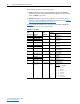
The Feedback can also be viewed in two ways:
• FREQ OUTPUT (point 03), PCT OUTPUT (point 04), and SPEED
(point 05) report the feedback in values such as Hz, percent of maximum
speed, and RPM, respectively.
• FEEDBACK (point 91) reports the feedback as a scaled value. For an
explanation of how the Reference/Feedback is scaled, refer to the Setting
the Logic Command and Reference on page 6-5.
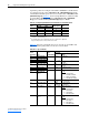
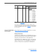
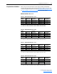
Table 6.E
shows the status that you can view on a PowerFlex 70/700 drive
and the points that you can use to view them.
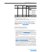
Table 6.E Logic Status
Point
Number(s) Point Name
Logic
Status Bit
PowerFlex 70/700 Example
Descriptio
n Values
(1)
25 READY 0 Ready 0 = Not Ready
1 = Ready
95 LOGIC STS LO bit 0
23 RUN.STOP MON 1 Active 0 = Not Running
1 = Running
95 LOGIC STS LO bit 1
95 LOGIC STS LO bit 2 2 Command
Direction
0 = Reverse
1 = Forward
21 FWD.REV MON 3 Actual
Direction
0 = Reverse
1 = Forward
95 LOGIC STS LO bit 3
95 LOGIC STS LO bit 4 4 Accel 0 = Not Accelerating
1 = Accelerating
95 LOGIC STS LO bit 5 5 Decel 0 = Not Decelerating
1 = Decelerating
95 LOGIC STS LO bit 6 6 Alarm 0 = No Alarm
1 = Alarm
93 OK.FAULT 7 Fault 0 = No Fault
1 = Fault
95 LOGIC STS LO bit 7
96 LOGIC STS HI bit 0 8 At Speed 0 = Not At Reference
1 = At Reference
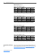
96 LOGIC STS HI
bits 3, 2, 1
9, 10, and 11 Local
Control
LOGIC STS HI Bits
03 02 01
000= Port 0 (TB)
001= Port 1
010= Port 2
011= Port 3
100= Port 4
101= Port 5
110= Port 6
111= No Local