
User Manual

Installing the Adapter 2-7
20-COMM-H RS-485 HVAC Adapter User Manual
Publication 20COMM-UM009D-EN-P
Applying Power
Install the drive cover or close the drive door, and apply power to the drive.
The adapter receives its power from the connected drive. When you apply
power to the adapter for the first time, its topmost “PORT” status indicator
should be steady green after an initialization. If it is red, there is a problem.
Refer to Chapter 8
, Troubleshooting.
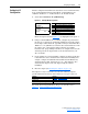
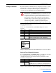
Start-Up Status Indications
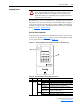
Status indicators for the drive and communications adapter can be viewed
on the front of the drive (Figure 2.6
) after power has been applied. Possible
start-up status indications are shown in Table 2.A
.
Figure 2.6 Drive and Adapter Status Indicators (location on drive may vary)
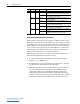
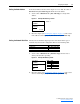
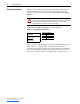
Table 2.A Drive and Adapter Start-Up Status Indications
!
ATTENTION: Risk of equipment damage, injury, or death
exists. Unpredictable operation may occur if you fail to verify
that parameter settings are compatible with your application.
Verify that settings are compatible with your application before
applying power to the drive.
Item Name Color State Description
Drive STS Indicator
➊
STS
(Status)
Green Flashing Drive ready but not running, and no faults are present.
Steady Drive running, no faults are present.
Yellow Flashing,
Drive Stopped
An inhibit condition exists – the drive cannot be started.
Check drive Parameter 214 - [Start Inhibits].
Flashing, Drive
Running
An intermittent type 1 alarm condition is occurring.
Check drive Parameter 211 - [Drive Alarm 1].
Steady,
Drive Running
A continuous type 1 alarm condition exists. Check drive
Parameter 211 - [Drive Alarm 1].
Red Flashing A fault has occurred.
Steady A non-resettable fault has occurred.
➋
➊
PORT
MOD
STS
NET A
NET B