20-COMM-H RS-485 HVAC Adapter Firmware Version 2.
Important User Information Solid state equipment has operational characteristics differing from those of electromechanical equipment. Safety Guidelines for the Application, Installation and Maintenance of Solid State Controls (Publication SGI-1.1 available from your local Rockwell Automation sales office or online at http:// www.rockwellautomation.com/literature) describes some important differences between solid state equipment and hard-wired electromechanical devices.
Summary of Changes The information below summarizes the changes made to this manual since its last release (March 2004): Description of Changes Reformatted document from half size (5.5 x 8.5 in.) to full size (8.5 x 11 in.) Page Throughout manual Added SMC Flex to the list of compatible products, and Metasys N2 is compatible with 1-2 PowerFlex 700VC drive. Added new Adapter Modbus Register Map section. 4-2 Included information about using Modbus RTU mode to access 16-bit and 32-bit 4-10 and parameters.
soc-ii Summary of Changes 20-COMM-H RS-485 HVAC Adapter User Manual Publication 20COMM-UM009D-EN-P
Table of Contents Preface About This Manual Related Documentation . . . . . . . . . . . . . . . . . . . . . . . . . . . . . . . . . . . . . . . . . . . . . . . . . . P-1 Rockwell Automation Support . . . . . . . . . . . . . . . . . . . . . . . . . . . . . . . . . . . . . . . . . . . . . P-2 Conventions Used in This Manual . . . . . . . . . . . . . . . . . . . . . . . . . . . . . . . . . . . . . . . . . . P-2 Chapter 1 Getting Started Components. . . . . . . . . . . . . . . . . . . . . . . . . . . . . . .
ii Table of Contents Chapter 6 Using Siemens Building Technologies P1 FLN Understanding Siemens Building Technologies P1 FLN . . . . . . . . . . . . . . . . . . . . . . . . . 6-1 Using the P1 FLN Point Map for I/O . . . . . . . . . . . . . . . . . . . . . . . . . . . . . . . . . . . . . . . . 6-5 Using the P1 FLN Point Map to Access Parameters . . . . . . . . . . . . . . . . . . . . . . . . . . . . . 6-9 Chapter 7 Using Datalinks with All Protocols Using Datalinks . . . . . . . . . . . . . . . . . . .
Preface About This Manual Topic Related Documentation Rockwell Automation Support Conventions Used in This Manual Page P-1 P-2 P-2 Related Documentation For: DriveExplorer™ Refer to: http://www.ab.com/drives/driveexplorer, and DriveExplorer online help (installed with the software) DriveTools™ SP (includes http://www.ab.
P-2 About This Manual Rockwell Automation Support Rockwell Automation, Inc. offers support services worldwide, with over 75 sales/support offices, over 500 authorized distributors, and over 250 authorized systems integrators located through the United States alone. In addition, Rockwell Automation, Inc. representatives are in every major country in the world. Local Product Support Contact your local Rockwell Automation, Inc.
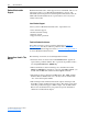
Chapter 1 Getting Started The adapter is a communication option intended for installation into a PowerFlex 7-Class drive. It can also be used with other Allen-Bradley products that support a DPI™ (Drive Peripheral Interface) adapter. Topic Components Features Compatible Products Required Equipment Safety Precautions Quick Start Status Indicators Components Figure 1.
1-2 Getting Started Features The adapter features include: • Typical mounting in a PowerFlex 7-Class drive using captive screws to secure and ground the adapter to the drive. • Compatibility with various configuration tools to configure the adapter and connected drive. The tools include the PowerFlex HIM on the drive, and drive-configuration software such as DriveExplorer (version 2.01 or higher) or DriveExecutive (version 3.01 or higher).
Getting Started Required Equipment 1-3 Equipment Shipped with the Adapter When you unpack the adapter, verify that the package includes: ❑ One adapter ❑ A 2.54 cm (1 in.) and a 15.24 cm (6 in.) Internal Interface cable (only one cable is needed to connect the adapter to the drive) User-Supplied Equipment To install and configure the adapter, you must supply: ❑ A small flathead screwdriver ❑ Network-specific cable to connect the adapter to the network.
1-4 Getting Started ! ! ! ! ! 20-COMM-H RS-485 HVAC Adapter User Manual Publication 20COMM-UM009D-EN-P ATTENTION: Risk of injury or equipment damage exists. Parameter 15 - [Comm Flt Action] lets you determine the action of the adapter and connected drive if communications are disrupted. By default, this parameter faults the drive. You can set this parameter so that the drive continues to run.
Getting Started Quick Start 1-5 This section is provided to help experienced users quickly start using the adapter. If you are unsure how to complete a step, refer to the referenced chapter. Step 1 2 3 Action Review the safety precautions for the adapter. Verify that the PowerFlex drive is properly installed. Commission the adapter. 4 Select the network protocol using the adapter Network Selector switch.
1-6 Getting Started Status Indicators The adapter uses four status indicators to report its operating status. They can be viewed on the adapter or through the drive cover (Figure 1.2). Figure 1.2 Status Indicators (location on drive may vary) ➊ ➋ ➌ ➍ ➊ ➋ ➌ ➍ Item Name ➊ PORT ➋ ➌ ➍ MOD NET A NET B After installing the adapter and applying power to the drive, refer to Start-Up Status Indications on page 2-7 for possible start-up status indications and their descriptions.
Chapter 2 Installing the Adapter This chapter provides instructions for installing the adapter in a PowerFlex 7-Class drive. Topic Preparing for an Installation Commissioning the Adapter Connecting the Adapter to the Drive Connecting the Adapter to the Network Applying Power Page 2-1 2-1 2-3 2-6 2-7 Preparing for an Installation Before installing the adapter, verify that you have all required equipment. Refer to Required Equipment on page 1-3.
2-2 Installing the Adapter 1. Set the adapter’s node address by rotating the node address switches to the desired value for each digit. Important: Each node on the network must have a unique address. Figure 2.1 Setting the Node Address 2 2 3 4 1 0 5 9 6 7 8 Setting 01 – 99 00 (Default) 3 4 1 0 5 9 6 8 7 Description Node address used by the adapter.
Installing the Adapter Connecting the Adapter to the Drive ! 2-3 ATTENTION: Risk of injury or death exists. The PowerFlex drive may contain high voltages that can cause injury or death. Remove power from the drive, and then verify power has been discharged before installing or removing the adapter. 1. Remove power from the drive and network. 2. Use static control precautions. 3. Remove the drive cover or open the drive door. 4.
2-4 Installing the Adapter Figure 2.3 DPI Ports and Internal Interface Cables 20-COMM-H Adapter ➊ ➋ ➌ PowerFlex 70 - All Frames ➍ PowerFlex 700 Frames 0 and 1 PowerFlex 700S Frames 0 and 1 PowerFlex 700 Frames 2 and Larger PowerFlex 700S Frames 2 through 6 HIM panel opens to allow access to DPI interface. To open panel, remove screws on left side of HIM panel and swing open. PowerFlex 700H Frames 9 and Larger PowerFlex 700S Frames 9 and Larger Item Description ➊ 15.24 cm (6 in.
Installing the Adapter Figure 2.4 2-5 Mounting and Grounding the Adapter Drive 0.9 N•m (8.0 lb•in) 4 Places Adapter Internal Interface Cable folded behind the adapter and in front of the drive. Ground Tab Detail PowerFlex 70 - All Frame Sizes (Adapter mounts in drive.) 0.9 N•m (8.0 lb•in) 4 Places PowerFlex 700 Frames 0 and 1 PowerFlex 700S Frames 0 and 1 (Adapter mounts on door.) Verify metal ground tab is bent 90° and is under the adapter before tightening screw.
2-6 Installing the Adapter Connecting the Adapter to the Network ATTENTION: Risk of injury or death exists. The PowerFlex drive may contain high voltages that can cause injury or death. Remove power from the drive, and then verify power has been discharged before installing or removing the adapter. ! 1. Remove power from the network and drive. 2. Use static control precautions. 3. Connect an RS-485 cable to the network, and route it through the bottom of the PowerFlex drive (Figure 2.4). 4.
Installing the Adapter Applying Power 2-7 ATTENTION: Risk of equipment damage, injury, or death exists. Unpredictable operation may occur if you fail to verify that parameter settings are compatible with your application. Verify that settings are compatible with your application before applying power to the drive. ! Install the drive cover or close the drive door, and apply power to the drive. The adapter receives its power from the connected drive.
2-8 Installing the Adapter Item Name Color ➋ PORT Green MOD Green NET A Green NET B Green State Description Adapter Status Indicators Flashing Normal Operation. The adapter is establishing an I/O connection to the drive. It will turn solid green or red. Steady Normal Operation. The adapter is properly connected and communicating with the drive Flashing Normal Operation. The adapter is operating but is not transferring I/O data. Steady Normal Operation.
Chapter 3 Configuring the Adapter This chapter provides instructions and information for setting the parameters in the adapter.
3-2 Configuring the Adapter Using the PowerFlex 7-Class If your drive has either an LED or LCD HIM (Human Interface Module), it can be used to access parameters in the adapter as shown below. It is HIM recommended that you read through the steps for your HIM before performing the sequence. For additional information, refer to your PowerFlex Drive User Manual or the HIM Quick Reference card. Using an LED HIM Step 1. Press ALT and then Sel (Device) to display the Device Screen.
Configuring the Adapter Setting the Node Address 3-3 If the Node Address switches on the adapter are set to “00,” the value of Parameter 03 - [Net Addr Cfg] determines the node address. 1. Set the value of Parameter 03 - [Net Addr Cfg] to a unique node address. Figure 3.1 Example Net Addr Cfg 1 Screen Default = 1 Port 5 Device 20-COMM-H Parameter #: 03 Net Addr Cfg 1 0 <> 247 2. Reset the adapter (see Resetting the Adapter on page 3-8).
3-4 Configuring the Adapter Setting the Network Parity The parity that the adapter uses to verify data integrity varies based on the type of network and your network configuration. Refer to the following table. Network Modbus RTU Metasys N2 Siemens Building Technologies P1 FLN Possible Types of Parity None, Even, or Odd None None 1. Set the value of Parameter 07 - [Net Parity Cfg] to the type of parity that is used on the network. Figure 3.
Configuring the Adapter Setting the I/O Configuration 3-5 The I/O configuration determines the data that is sent to and from the drive. Logic Command/Status, Reference/Feedback, and Datalinks may be enabled or disabled. A “1” enables the I/O. A “0” disables the I/O. 1. Set the bits in Parameter 16 - [DPI I/O Cfg]. Figure 3.
3-6 Configuring the Adapter Setting a Network Time-out The network timeout sets an interval within which the adapter must communicate with its master. If this time is exceeded, the adapter determines a loss of network communications has occurred and responds with the action specified in Parameter 15 - [Comm Flt Action]. By default, the timeout is set to ten (10) seconds. You can increase or decrease this value.
Configuring the Adapter Setting a Fault Action 3-7 By default, when I/O communications are disrupted (for example, a cable is disconnected), the drive responds by faulting if it is using I/O from the network. You can configure a different response to disrupted I/O communication using Parameter 15 - [Comm Flt Action]. ATTENTION: Risk of injury or equipment damage exists. Parameter 15 - [Comm Flt Action] lets you determine the action of the adapter and connected drive if I/O communications are disrupted.
3-8 Configuring the Adapter Resetting the Adapter Changes to switch settings and some adapter parameters require that you reset the adapter before the new settings take effect. You can reset the adapter by cycling power to the drive or by using Parameter 14 - [Reset Module]. ! ATTENTION: Risk of injury or equipment damage exists. If the adapter is transmitting control I/O to the drive, the drive may fault when you reset the adapter.
Configuring the Adapter The following parameters provide information about the status of the adapter. You can view these parameters at any time. Parameter 04 - [Net Add Act] 06 - [Net Rate Act] 08 - [Net Parity Act] 09 - [Stop Bits Act] Description Displays the actual network address of the adapter. Displays the network data rate actually used by the adapter. Only valid values for the specified network are displayed. Displays the actual network parity used by the adapter.
3-10 Configuring the Adapter Flash Updating the Adapter The adapter can be flash updated over the network or serially through a direct connection from a computer to the drive using a 1203-USB or 1203-SSS serial converter. When flashing over the network, you can use the Allen-Bradley software tool ControlFLASH, the built-in flash capability of DriveExplorer Lite or Full, or the built-in flash capability of DriveExecutive.
Chapter 4 Using Modbus RTU This chapter provides information about controlling a PowerFlex 7-Class drive, setting its Reference, and accessing its parameters through configurable objects when the Modbus RTU network protocol is selected. Topic Understanding Modbus RTU Using the Modbus RTU Point Map for I/O Accessing Drive Parameters Using Broadcast Messages Page 4-1 4-4 4-9 4-12 TIP: Datalinks can also be used for accessing parameters.
4-2 Using Modbus RTU Supported Modbus RTU Commands The adapter supports the Modbus RTU commands listed in Table 4.B. Table 4.
Using Modbus RTU 4-3 Table 4.
4-4 Using Modbus RTU Table 4.
Using Modbus RTU 4-5 Setting the Logic Command and Reference ! ATTENTION: Select and use either the “Product Logic Command Discrete Outputs (0x000x)” or the “Product Logic Command Register Output (4x0001)” as a control method, but not both. Conflicts caused from using both methods can result in dangerous operation. Failure to observe this caution could cause bodily injury and/or damage to equipment. On Modbus RTU, there are two ways to set the logic command: discrete outputs (Table 4.
4-6 Using Modbus RTU Table 4.E shows that there are 16 discrete points to represent the command word bit by bit. These points can be used only for writing single-bit commands. Table 4.
Using Modbus RTU 4-7 Table 4.F shows the register outputs. These outputs must be used for writing multi-bit commands and the Reference. Table 4.F Logic Command and Reference: Register Outputs Modbus Address 4x0001 Output Description Product Logic Command 4x0002 Reference Lo 4x0003 (1) Reference Hi (1) Values 16-bit word. Bit definitions for PowerFlex 70/700 drives are in Table 4.E. For other products, refer to their documentation. Bit 0…15 of 32-bit reference.
4-8 Using Modbus RTU Table 4.
Using Modbus RTU Accessing Drive Parameters 4-9 There are two methods for accessing drive parameters: the direct access method and the pointer access method. Direct Access Method You can use Function Code 03 to read and Function Codes 06 (single) and 16 (multiple) to write, to directly access the drive parameters (see Table 4.B on page 4-2).
4-10 Using Modbus RTU Figure 4.1 Configurable Input Point Operations Write Single Register (code 06) or Write Multiple Register (code 16) Controller Param# for INx Adapter and Drive Read Input Registers (code 04) Request Response Data User INx With the adapter in 16-bit mode, 8 User IN items are available. Table 4.
Using Modbus RTU 4-11 store the returned 16-bit data. Use both 16-bit data items to make one 32-bit value for drive parameter 12. Writing Parameter Values ! ATTENTION: Risk of equipment damage exists. If configurable output points are programmed to write parameter data to Non-Volatile Storage (NVS) frequently, the NVS will quickly exceed its life cycle and cause the drive to malfunction. Do not create a program that frequently uses configurable outputs to write parameter data to NVS.
4-12 Using Modbus RTU Table 4.K Configurable Objects: Outputs with Adapter in 16-bit Mode Modbus Address 4x0012 4x0013 4x0014 4x0015 4x0016 4x0017 Data Direction Register Output Description User OUT1 User OUT2 User OUT3 Param # for OUT1 Param # for OUT2 Param # for OUT3 Values Depends on parameter selected 0 = Not in use - or 1 to maximum parameter # User Default 0 0 16-bit Mode Example: Write a value of “101” to register 4x0015. Write a value of “123” to register 4x0012.
Using Modbus RTU Adapter Parameter Direct Access 4-13 Table 4.L provides an overview of the Modbus register addresses for directly accessing the adapter parameters. Table 4.
4-14 Using Modbus RTU Notes: 20-COMM-H RS-485 HVAC Adapter User Manual Publication 20COMM-UM009D-EN-P
Chapter 5 Using Metasys N2 This chapter provides information about controlling a PowerFlex 7-Class drive, setting its Reference, and accessing its parameters through configurable objects when the Metasys N2 network protocol is selected. Topic Understanding Metasys N2 Using the Metasys N2 Point Map for I/O Using Metasys Configurable Objects to Access Parameters Page 5-1 5-3 5-8 TIP: Datalinks can also be used for accessing parameters.
5-2 Using Metasys N2 Table 5.A Description of the Regions of a Virtual Object Region Region 1 Region 2 Region 3 Region 4 Region 5 Region 6 Region 7 Type Analog Input Binary Input Analog Output Binary Output Internal Float Internal Integer Internal Byte Short AI BI AO BO ADF ADI DB Description 32-bit, IEEE-standard floats 1-bit 32-bit, IEEE-standard floats 1-bit 32-bit, IEEE-standard floats (Analog Data Float) 16-bit (Analog Data Integer) 8-bit (Analog Data Byte) Metasys N2 Data Types Table 5.
Using Metasys N2 Using the Metasys N2 Point Map for I/O 5-3 On Metasys N2, data transfers are used to transfer the I/O data that controls the drive and sets its Reference. Note that Output I/O is data that the master device sends and the adapter receives. Input I/O is status data that the adapter sends and the master device receives. Important: In order for the drive to use the I/O and Reference from the Metasys N2 network, you must set parameters in it and the adapter to receive the I/O and Reference.
5-4 Using Metasys N2 Table 5.G Example Speed Reference and Feedback for a PowerFlex 70/700 Drive Reference (1) Percent 100% 50% 25% 0% Speed 70 Hz 35 Hz 17.5 Hz 0 Hz Feedback (2) Speed 60 Hz (3) 35 Hz 17.5 Hz 0 Hz Percent 85.7% 50% 25% 0% (1) The actual value transmitted over the network is an engineering unit where 100% equals sending the value in the adapter Parameter 29 - [N2 Ref Scale], and 0% equals sending a zero.
Using Metasys N2 5-5 Table 5.L shows that there are 16 binary outputs to represent the command word bit by bit. These outputs can be used only for writing single-bit commands. Table 5.
5-6 Using Metasys N2 Table 5.M shows the analog outputs. These outputs must be used for writing multi-bit commands and the Reference. Table 5.M Logic Command and Reference: Analog Outputs Network Point Network Point Parameter Type (NPT) Address (NPA) Description AO 1 Product Logic Command AO 2 Reference Range 16-bit word. Bit definitions for PowerFlex 70/700 drives are in Table 5.L. For other products, refer to their documentation. -100.0…100.
Using Metasys N2 5-7 Table 5.N shows that there are 16 binary inputs to represent the status word bit by bit. These inputs can be used only for reading single-bit status. Table 5.
5-8 Using Metasys N2 Table 5.O Logic Status and Feedback: Analog Inputs Network Point Network Point Parameter Type (NPT) Address (NPA) Description AI 1 Product Status Word AI 2 Feedback Lo Range 16-bit word. Bit definitions for PowerFlex 70/700 drives are in Table 5.N. For other products, refer to their documentation. -100.0…100.0% Configurable objects are inputs and outputs that let you read and write Using Metasys Configurable Objects to Access Parameters parameter values.
Using Metasys N2 5-9 Table 5.Q Example of Configurable Objects: Inputs Network Point Type (NPT) AI AI AI AI Network Point Address (NPA) 3 4 5 6 Name Output Frequency Output Current Output Voltage Output Power Description -400…400 Hz [0.1 Hz] 0.0 to Drive Related Amps [0.1 A] 0.0 to Drive Related Volts [0.1 VAC] 0.0 to Drive Related kW [0.1 kW] Default 60.0 14.0 460.0 7.
5-10 Using Metasys N2 Notes: 20-COMM-H RS-485 HVAC Adapter User Manual Publication 20COMM-UM009D-EN-P
Chapter 6 Using Siemens Building Technologies P1 FLN This chapter provides information about controlling a PowerFlex 7-Class drive, setting its Reference, and accessing its parameters through points when the Siemens Building Technologies P1 FLN network protocol is selected. Topic Understanding Siemens Building Technologies P1 FLN Using the P1 FLN Point Map for I/O Using the P1 FLN Point Map to Access Parameters Page 6-1 6-5 6-9 TIP: Datalinks can also be used for accessing parameters.
6-2 Using Siemens Building Technologies P1 FLN P1 FLN Point Types Logic analog and digital I/O points are used for controlling the drive, monitoring status, and reading/writing parameters. Table 6.A shows the four point types. Table 6.A Point Types Abbreviation Name LDI Logical Digital Inputs LDO LAI LAO Used for Reading bit level points (0 or 1) such as drive status. For example, FWD.REV MON (point 21) provides the status of the rotation direction of the drive.
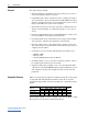
LAO LAO LAI LAO LAO LAI {32} 36 {37} 38 39 {44} (4) (3) (2) PARAM IN USER IN PARAM OUT USER OUT DLNK A1 OUT DECEL TIME READY RUN ENABLE DAY.NGT CURRNT LIMIT ACCEL TIME Descriptor CTRL ADDRESS APPLICATION FREQ OUTPUT PCT OUTPUT SPEED CURRENT TORQUE POWER DRIVE TEMP DRIVE MWH RUN TIME DC BUS VOLT OVRD TIME FWD.REV MON CMD FWD.REV RUN.STOP MON CMD RUN.STOP 1 1 1 1 1 0.1 1 1 1 0.1 0.1 English Units Slope 1 1 HZ 0.01 PCT 0.1 RPM 1 AMPS 0.1 PCT 0.1 KW 0.1 DEG C 0.1 MWH 0.1 HRS 0.1 VOLTS 0.
20-COMM-H RS-485 HVAC Adapter User Manual Publication 20COMM-UM009D-EN-P (3) (2) LOGIC STS LO LOGIC STS HI ERROR STATUS Descriptor DLNK A2 OUT DLNK B1 OUT DLNK B2 OUT DLNK C1 OUT DLNK C2 OUT DLNK D1 OUT DLNK D2 OUT INPUT REF 1 INPUT REF 2 DLNK A1 IN DLNK A2 IN DLNK B1 IN DLNK B2 IN DLNK C1 IN DLNK C2 IN DLNK D1 IN DLNK D2 IN LOGIC CMD LO LOGIC CMD HI FEEDBACK REFERENCE OK.FAULT RESET FAULT 1 1 1 English Units Slope 1 1 1 1 1 1 1 0.001 0.
Using Siemens Building Technologies P1 FLN Using the P1 FLN Point Map for I/O 6-5 On Siemens Building Technologies P1 FLN, data transfers are used to transfer the I/O data that controls the drive and sets its Reference. Note that Output I/O is data that the master device sends and the adapter receives. Input I/O is status data that the adapter sends and the master device receives.
6-6 Using Siemens Building Technologies P1 FLN engineering value. For example, in PowerFlex 70/700 drives, the Reference is scaled based on the value of Parameter 55 - [Maximum Freq], but the commanded maximum speed can never exceed the value of Parameter 82 [Maximum Speed]. Table 6.C shows example References and their results on a PowerFlex 70/700 drive that has its Parameters 55 - [Maximum Freq] set to 130 Hz and 82 - [Maximum Speed] set to 60 Hz. Table 6.
Using Siemens Building Technologies P1 FLN 6-7 Table 6.
6-8 Using Siemens Building Technologies P1 FLN The Feedback can also be viewed in two ways: • FREQ OUTPUT (point 03), PCT OUTPUT (point 04), and SPEED (point 05) report the feedback in values such as Hz, percent of maximum speed, and RPM, respectively. • FEEDBACK (point 91) reports the feedback as a scaled value. For an explanation of how the Reference/Feedback is scaled, refer to the Setting the Logic Command and Reference on page 6-5. Table 6.
Using Siemens Building Technologies P1 FLN 6-9 Table 6.
6-10 Using Siemens Building Technologies P1 FLN Writing Parameter Values ! ATTENTION: Risk of equipment damage exists. If configurable points are programmed to write parameter data to Non-Volatile Storage (NVS) frequently, the NVS will quickly exceed its life cycle and cause the drive to malfunction. Do not create a program that frequently uses configurable points to write parameter data to NVS. Datalinks do not write to NVS and should be used for frequently changed parameters.
Chapter 7 Using Datalinks with All Protocols This chapter provides information and examples showing how to use Datalinks. Topic Using Datalinks Using Datalinks with Modbus Using Datalinks with Metasys N2 Using Datalinks with Siemens P1 FLN Using Datalinks Page 7-1 7-3 7-4 7-5 A Datalink is a mechanism used by PowerFlex drives to transfer data to and from the controller. Datalinks “point” to specific drive parameters to be accessed.
7-2 Using Datalinks with All Protocols 32-bit data is stored in binary as follows: MSW LSW 231 through 216 215 through 20 In this example, the Parameter 10 - [Elapsed Run Time] value of 6553.9 Hrs is read as “6553.9” in Datalink A1 Out and Datalink A2 Out. Datalink A1 Out A2 Out Word LSW MSW Parameter 10 10 Data (Hex) 0003 0001 Conversion Example: Parameter 010 - [Elapsed Run Time] = 6553.
Using Datalinks with All Protocols Using Datalinks with Modbus 7-3 This section presents information about using Datalinks with Modbus networks. For information about using Datalinks for Metasys N2 networks or Siemens P1 FLN networks, refer to the Using Datalinks with Metasys N2 or Using Datalinks with Siemens P1 FLN sections in this chapter. Modbus Datalinks Out: A…D Table 7.
7-4 Using Datalinks with All Protocols Modbus Datalinks In: A…D Table 7.
Using Datalinks with All Protocols 7-5 Metasys N2 Datalinks Out: A and B (No Datalinks C and D) Table 7.I Metasys N2 Datalinks Out - A1, A2 Network Point Network Point Parameter 16-Bit Type (NPT) Address (NPA) Direction Description Datalink AI 7 Input Datalink A1 Out 16-bit value AI 8 Input Datalink A2 Out 16-bit value 32-Bit Datalink Limited to -16,777,215…16,777,215 Limited to -16,777,215…16,777,215 Table 7.
7-6 Using Datalinks with All Protocols Note that certain drives may utilize 32-bit datalinks. In this case, Datalinks are not supported by the adapter. The adapter will support only 15-bit Datalink values. ! ATTENTION: Risk of injury or equipment damage exists. On P1 FLN networks, 16-bit values are truncated to 15-bit values. Unpredictable operation may result from using non-16-bit drive parameters with the configurable points.
Chapter 8 Troubleshooting This chapter provides information for diagnosing and troubleshooting potential problems with the adapter and network. Topic Understanding the Status Indicators PORT Status Indicator MOD Status Indicator NET A Status Indicator NET B Status Indicator Viewing Adapter Diagnostic Items Viewing and Clearing Events Understanding the Status Indicators Page 8-1 8-2 8-2 8-3 8-3 8-4 8-6 The adapter has four status indicators. They can be viewed on the adapter or through the drive cover.
8-2 Troubleshooting PORT Status Indicator This red/green bicolor LED indicates the status of the adapter’s DPI connection to the drive as shown in the table below. Status Off Cause The adapter is not powered or is not properly connected to the drive. Corrective Action • Securely connect the adapter to the drive using the Internal Interface (ribbon) cable. Flashing Red The adapter is not receiving a ping message from the drive. • Apply power to the drive.
Troubleshooting 8-3 Status Cause Corrective Action Flashing Green The adapter is operational, but is not transferring I/O • Place the scanner in RUN mode. data. • Program the controller to recognize and transmit I/O to the adapter. • Configure the adapter for the program in the controller. Flashing Red/ Green Steady Green • Normal behavior if all I/O has been disabled in Parameter 16 - [DPI I/O Cfg]. The adapter has detected a framing error.
8-4 Troubleshooting Viewing Adapter Diagnostic If you encounter unexpected communications problems, the adapter’s diagnostic items may help you or Rockwell Automation personnel Items troubleshoot the problem. Adapter diagnostic items can be viewed using an LCD PowerFlex 7-Class HIM (Diagnostics/Device Items), DriveExplorer software (version 2.01 or higher), or DriveExecutive software (version 1.01 or higher). Using the HIM to View Adapter Diagnostic Items Step 1. Access parameters in the adapter.
Troubleshooting 8-5 Table 8.A Adapter Diagnostic Items (Continued) No.
8-6 Troubleshooting Viewing and Clearing Events The adapter has an event queue to record significant events that occur in the operation of the adapter. When such an event occurs, an entry is put into the event queue. You can view the event queue using an LCD PowerFlex 7-Class HIM, DriveExplorer (2.01 or higher) software, DriveExecutive (1.01 or higher) software or other clients using the DPI Fault object. The event queue can contain up to 32 entries.
Troubleshooting 8-7 Events Many events in the event queue occur under normal operation. If you encounter unexpected communications problems, the events may help you or Allen-Bradley personnel troubleshoot the problem. The following events may appear in the event queue: Table 8.B Adapter Events Code Event 1 No Event 2 DPI Bus Off Flt 3 4 5 6 7 8 9 10 11 12 13 14 15 16 17 18 19 20 21 22 23 24 25 26 27 Description Empty event queue entry. A bus-off condition was detected on DPI.
8-8 Troubleshooting Notes: 20-COMM-H RS-485 HVAC Adapter User Manual Publication 20COMM-UM009D-EN-P
Appendix A Specifications Appendix A presents the specifications for the adapter.
A-2 Specifications Regulatory Compliance Certification UL cUL CE CTick Specification UL508C CAN / CSA C22.2 No. 14-M91 EN50178 and EN61800-3 EN61800-3 NOTE: This is a product of category C2 according to IEC 61800-3. In a domestic environment this product may cause radio interference in which case supplementary mitigation measures may be required.
Appendix B Adapter Parameters Appendix B provides information about the adapter parameters. Topic Parameter List Page B-1 Parameter List Parameter No. Name and Description 01 [DPI Port] 02 03 04 05 06 07 08 Details Default: Minimum: Displays the port to which the adapter is connected. Maximum: This will usually be port 5. Type: Default: [DPI Data Rate] Displays the data rate used by the drive. This data rate Values: is set in the drive and the adapter detects it.
B-2 Adapter Parameters Parameter No. Name and Description 09 [Stop Bits Act] Displays the actual number of stop bits used by the selected protocol. This value is network-dependent: Details Default: Values: Type: 0 = 1-bit 0 = 1-bit 1 = 2-bits Read Only • ModBus RTU Protocol – The number of stop bits used depends on the value set by Parameter 30 [Stop Bits Cfg]. • Metasys N2 Protocol – Uses only 1 bit, so the adapter shows only this value.
Adapter Parameters Parameter No. Name and Description 15 [Comm Flt Action] Details Default: Sets the action that the adapter will take if it detects a Values: network failure because it has not communicated with its master within the interval specified in Parameter 11 - [Network Timeout]. This action takes effect only if I/O that controls the drive is transmitted through the Type: adapter.
B-4 Adapter Parameters Parameter No. Name and Description 20 [Flt Cfg A1 In] 21 [Flt Cfg A2 In] 22 [Flt Cfg B1 In] 23 [Flt Cfg B2 In] 24 [Flt Cfg C1 In] 25 [Flt Cfg C2 In] 26 [Flt Cfg D1 In] 27 [Flt Cfg D2 In] Details Default: Default: Default: Default: Default: Default: Default: Default: Sets the data that is sent to the Datalink in the drive if Minimum: Parameter 15 - [Comm Flt Action] is set to “4” (Send Maximum: Type: Flt Cfg) and the adapter times out.
Appendix C Logic Command/Status Words Appendix D presents the definitions of the Logic Command and Logic Status words that are used for some products that can be connected to the adapter. If you do not see the Logic Command/Logic Status for the product that you are using, refer to your product’s documentation.
C-2 Logic Command/Status Words Logic Status Word Logic Bits 15 14 13 12 11 10 9 8 7 6 5 4 3 2 1 x x x x x x x x x x (1) x x x x x See “Owners” in drive User Manual for further information.
Logic Command/Status Words PowerFlex 700S Drives C-3 Logic Command Word (Phase II Control) Logic Bits 15 14 13 12 11 10 9 8 7 6 5 4 3 2 1 x x x x x x x x x x x x x x x 0 x Command Normal Stop Start (1) Jog 1 Clear Fault (2) Unipolar Direction Reserved Jog 2 Current Limit Stop Coast Stop Reserved Reserved Spd Ref Sel0 Spd Ref Sel1 Spd Ref Sel2 Description 0 = Not Normal Stop 1 = Normal Stop 0 = Not Start 1 = Start 0 = Not Jog using [Jog Speed 1] 1 = Jog using [Jog Speed 1] 0 = Not Clear F
C-4 Logic Command/Status Words Logic Status Word (Phase II Control) Logic Bits 15 14 13 12 11 10 9 8 7 6 5 4 3 2 1 x x x x x x x x x x x x x x x (1) 0 x Status Active Running Command Direction Actual Direction Accel Decel Jogging Fault Alarm Flash Mode Run Ready At Limit (1) Tach Loss Sw At Zero Spd At Setpt Spd Enable Description 0 = Not Active 1 = Active 0 = Not Running 1 = Running 0 = Reverse 1 = Forward 0 = Reverse 1 = Forward 0 = Not Accelerating 1 = Accelerating 0 = Not Decelerating 1 =
Glossary A Adapter Devices such as drives, controllers, and computers usually require an adapter to provide a communication interface between them and a network. An adapter reads data on the network and transmits it to the connected device. It also reads data in the device and transmits it to the network. The 20-COMM-H RS-485 HVAC adapter connects a PowerFlex 7-Class drive to the network. Adapters are sometimes also called “cards,” “embedded communication options,” “gateways,” “modules,” and “peripherals.
G-2 Glossary DPI Peripheral A device that provides an interface between DPI and a network or user. Peripheral devices are also referred to as “adapters” or “modules.” The 20-COMM-H adapter and PowerFlex 7-Class HIMs (20-HIM-xxx) are examples of DPI peripherals. DPI Product A device that uses the DPI communications interface to communicate with one or more peripheral devices. For example, a motor drive such as a PowerFlex 7-Class drive is a DPI product.
Glossary H G-3 HIM (Human Interface Module) A device that can be used to configure and control a drive. PowerFlex 7-Class HIMs (20-HIM-xxx) can be used to configure PowerFlex 7-Class drives and their connected peripherals. Hold Last When communication is disrupted (for example, a cable is disconnected), the adapter and PowerFlex drive can respond by holding last. Hold last results in the drive receiving the last data received via the network connection before the disruption.
G-4 Glossary Ping A message that is sent by a DPI product to its peripheral devices. They use the ping to gather data about the product, including whether it can receive messages and whether they can log in for control. PowerFlex 7-Class (Architecture Class) Drives The Allen-Bradley PowerFlex 7-Class family of drives supports DPI and includes the PowerFlex 70, PowerFlex 700, PowerFlex 700H, PowerFlex 700S, PowerFlex 700L, and PowerFlex 7000. These drives can be used for applications ranging from 0.
Index A adapter applying power, 2-7 commissioning, 2-1 compatible products, 1-2 components, 1-1 configuration tools, 3-1 configuring I/O for, 3-5 connecting to a drive, 2-3 connecting to the network, 2-6 definition, G-1 features, 1-2 flash updating, 3-10 grounding, 2-5 installation, 2-1 to 2-8 mounting on the drive, 2-5 parameters, B-1 to B-4 resetting, 3-8 selecting operating mode, B-4 specifications, A-1 viewing its status, 3-9 ControlFLASH, G-1 controller, G-1 D data rate definition, G-1 setting, 3-3 d
Index-2 environmental specifications, A-1 equipment required, 1-3 events clearing/viewing, 8-6 list of, 8-7 Internal Interface cables connecting to the adapter, 2-4 connecting to the drive, 2-4 illustration, 2-4 L F fault action configuring the adapter for, 3-7 definition, G-2 fault configuration configuring the adapter for, 3-7 definition, G-2 faults, see events features, 1-2 firmware release, P-2 flash update definition, G-2 guidelines, 3-10 Flt Cfg A1-D2 In parameters, B-4 Flt Cfg Logic parameter, B-3
Index-3 Net Addr Act parameter, B-1 power consumption, A-1 Net Addr Cfg parameter, B-1 NET B status indicator locating, 1-6 troubleshooting with, 8-3 PowerFlex drives compatible with adapter, 1-2 definition, G-4 HIM, 3-2 Net Chksum Type parameter, B-2 preparing for an installation, 2-1 Net Parity Act parameter, B-1 processor, see controller Net Parity Cfg parameter, B-1 programmable logic controller, see controller Net Rate Act parameter, B-1 Net Rate Cfg parameter, B-1 Q network cable, 2-6 dat
Index-4 T technical support, P-2 tools required, 1-3 troubleshooting, 8-1 to 8-7 Type 0/Type 1/Type 2 control, G-4 U update, see flash update W web site DriveExecutive software, G-2 DriveExplorer software, G-2 DriveTools SP software, G-2 manuals, P-1 wiring, see cables Z zero data configuring the adapter for, 3-7 definition, G-4 20-COMM-H RS-485 HVAC Adapter User Manual Publication 20COMM-UM009D-EN-P
U.S. Allen-Bradley Drives Technical Support - Tel: (1) 262.512.8176, Fax: (1) 262.512.2222, Email: support@drives.ra.rockwell.com, Online: www.ab.com/support/abdrives www.rockwellautomation.com Power, Control and Information Solutions Headquarters Americas: Rockwell Automation, 1201 South Second Street, Milwaukee, WI 53204 USA,Tel: (1) 414.382.2000, Fax: (1) 414.382.