PowerFlex 20-COMM-E EtherNet/IP Adapter Series A FRN 2.xxx Series B FRN 4.
0-COMM-E EtherNet/IP Adapter User Manual
Important User Information Solid state equipment has operational characteristics differing from those of electromechanical equipment. Safety Guidelines for the Application, Installation and Maintenance of Solid State Controls (Publication SGI-1.1 available from your local Rockwell Automation sales office or online at http:// www.rockwellautomation.com/literature) describes some important differences between solid state equipment and hard-wired electromechanical devices.
20-COMM-E EtherNet/IP Adapter User Manual
Summary of Changes The information below summarizes the changes made to this manual since its last release (October 2012): Description of Changes Page Added information about the compatible products. Throughout manual Added information for use with PowerFlex Digital DC drives.
soc-ii Summary of Changes Notes: 20-COMM-E EtherNet/IP Adapter User Manual Publication 20COMM-UM010G-EN-P
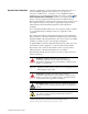
Table of Contents Preface About This Manual Conventions Used in This Manual . . . . . . . . . . . . . . . . . . . . . . . . . . . . . . . . . . . . . . . . . . P-1 Rockwell Automation Support . . . . . . . . . . . . . . . . . . . . . . . . . . . . . . . . . . . . . . . . . . . . . P-2 Additional Resources . . . . . . . . . . . . . . . . . . . . . . . . . . . . . . . . . . . . . . . . . . . . . . . . . . . . P-2 Chapter 1 Getting Started Components. . . . . . . . . . . . . . . . . . . . . . . . . . . . .
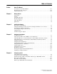
ii Table of Contents Chapter 5 Using the I/O About I/O Messaging. . . . . . . . . . . . . . . . . . . . . . . . . . . . . . . . . . . . . . . . . . . . . . . . . . . . . 5-1 Understanding the I/O Image. . . . . . . . . . . . . . . . . . . . . . . . . . . . . . . . . . . . . . . . . . . . . . . 5-2 Using Logic Command/Status . . . . . . . . . . . . . . . . . . . . . . . . . . . . . . . . . . . . . . . . . . . . . . 5-6 Using Reference/Feedback . . . . . . . . . . . . . . . . . . . . . . . . . . . . . . .
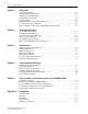
Table of Contents Appendix B iii Adapter Parameters Parameter List . . . . . . . . . . . . . . . . . . . . . . . . . . . . . . . . . . . . . . . . . . . . . . . . . . . . . . . . . . B-1 Appendix C EtherNet/IP Objects Identity Object. . . . . . . . . . . . . . . . . . . . . . . . . . . . . . . . . . . . . . . . . . . . . . . . . . . . . . . . . . C-2 Assembly Object . . . . . . . . . . . . . . . . . . . . . . . . . . . . . . . . . . . . . . . . . . . . . . . . . . . . . . . . C-3 Register Object . . .
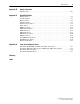
iv Table of Contents 20-COMM-E EtherNet/IP Adapter User Manual Publication 20COMM-UM010G-EN-P
Preface About This Manual Topic Page Conventions Used in This Manual P-1 Rockwell Automation Support P-2 Additional Resources P-2 This manual provides information about the adapter and using it with PowerFlex 7-Class (Architecture-Class) drives. The adapter can be used with other products that support a DPI™ adapter, such as the DPI External Comms Kit (20-XCOMM-DC-BASE). See the documentation for your product for specific information about how it works with the adapter.
P-2 About This Manual Rockwell Automation Support Rockwell Automation offers support services worldwide, with over 75 sales and support offices, over 500 authorized distributors, and over 250 authorized systems integrators located through the United States alone. In addition, Rockwell Automation representatives are in every major country in the world.
About This Manual P-3 Resource Description PowerFlex 700S w/Phase I Control Installation Manual (Frames 1…6), publication 20D-IN024 PowerFlex 700S w/Phase I Control Installation Manual (Frames 9 and 10), publication PFLEX-IN006 PowerFlex 700S w/Phase I Control User Manual (All Frame Sizes), publication 20D-UM001 PowerFlex 700S w/Phase I Control Reference Manual, publication PFLEX-RM002 PowerFlex 700S w/Phase II Control Installation Manual (Frames 1…6), publication 20D-IN024 PowerFlex 700S w/Phase II Con
P-4 About This Manual Notes: 20-COMM-E EtherNet/IP Adapter User Manual Publication 20COMM-UM010G-EN-P
Chapter 1 Getting Started The adapter is intended for installation in a PowerFlex 7-Class drive and is used for network communication. The 20-COMM-E Series B adapter, firmware 3.xxx or later, can also be installed in an External DPI Comms Kit (20-XCOMM-DC-BASE). For PowerFlex 750-Series drives, we recommend using the 20-750-ENETR Dual-port EtherNet/IP option module or the embedded EtherNet/IP adapter (only in PowerFlex 755 drives) instead of the 20-COMM-E adapter.
1-2 Getting Started Features The features of the adapter include the following: • Typical mounting in a PowerFlex 7-Class drive. The 20-COMM-E Series B adapter, firmware 3.xxx or later, can also be installed in a DPI External Comms Kit and used with the kit’s optional I/O board. See Chapter 9, Using the Adapter in a DPI External Comms Kit (20-XCOMM-DC-BASE) for more information.
Getting Started Compatible Products 1-3 At the time of publication, the adapter is compatible with the following products: • PowerFlex 70 drives with standard or enhanced control • PowerFlex 750-Series drives (1) • PowerFlex 700 drives with standard or vector control • PowerFlex Digital DC drives • PowerFlex 700H drives • DPI External Comms Kit • PowerFlex 700S drives with Phase I or Phase II control • SMC™ Flex smart motor controllers • PowerFlex 700L drives with 700 vector control or 700S contr
1-4 Getting Started ❑ Ethernet switch (for details, see the Ethernet Design Considerations Reference Manual, publication ENET-RM002) ❑ Drive and adapter configuration tool, such as the following: – PowerFlex 20-HIM-xx HIM – Connected Components Workbench software, version 1.02 or later Connected Components Workbench is the recommended stand-alone software tool for use with PowerFlex drives. You can obtain a free copy by: • Internet download at http://www.ab.com/support/abdrives/ webupdate/software.
Getting Started Safety Precautions 1-5 Please read the following safety precautions carefully. ! ! ! ! ! ! ! ATTENTION: Risk of injury or death exists. The PowerFlex drive may contain high voltages that can cause injury or death. Remove all power from the PowerFlex drive, and then verify power has been discharged before installing or removing an adapter. ATTENTION: Risk of injury or equipment damage exists.
1-6 Getting Started Quick Start This section is provided to help experienced users quickly start using the adapter. If you are unsure how to complete a step, refer to the referenced chapter. Step Action See 1 Review the safety precautions for the adapter. Throughout this manual 2 Verify that the PowerFlex drive is properly installed. Drive User Manual 3 Install the adapter. b. Connect the adapter to the drive with the Internal Interface cable.
Chapter 2 Installing the Adapter This chapter provides instructions for installing the adapter in a PowerFlex 7-Class drive. The 20-COMM-E Series B adapter, firmware revision 3.xxx or later, can also be installed in a DPI External Comms Kit. In this case, see Chapter 9 or the 20-XCOMM-DC-BASE Installation Instructions, publication 20COMM-IN001, supplied with the kit. Topic Page Preparing for an Installation 2-1 Setting the Web Pages Switch (only Series B Adapter, Firmware 3.
2-2 Installing the Adapter Much of EtherNet/IP implicit (I/O) messaging uses IP multicast to distribute I/O control data, which is consistent with the CIP producer/ consumer model. Historically, most switches have treated multicast packets the same as broadcast packets. That is, all multicast packets are re-transmitted to all ports.
Installing the Adapter Figure 2.1 2-3 Setting Web Pages Switch (only Series B Adapter) Unused Switch Web Pages Switch O1 2 N Enable Web Position Disable Web Position Connecting the Adapter to the Drive SW2 Setting Description Down (OFF) position Disables the adapter web pages (default setting) Up (ON) position Enables the adapter web pages ! ATTENTION: Risk of injury or death exists. The PowerFlex drive may contain high voltages that can cause injury or death.
2-4 Installing the Adapter Figure 2.2 DPI Ports and Internal Interface Cables 20-COMM-E Adapter ➊ ➋ ➌ PowerFlex 70 - All Frames ➍ PowerFlex 700 Frames 0 and 1 PowerFlex 700S Frames 0 and 1 PowerFlex 700 Frames 2 and Larger PowerFlex 700S Frames 2 through 6 HIM panel opens to allow access to DPI interface. To open panel, remove screws on left side of HIM panel and swing open.
Installing the Adapter Figure 2.3 2-5 Mounting and Grounding the Adapter Drive 0.9 N•m (8.0 lb•in) 4 Places Adapter Internal Interface Cable folded behind the adapter and in front of the drive. Ground Tab Detail PowerFlex 70 - All Frame Sizes (Adapter mounts in drive.) 0.9 N•m (8.0 lb•in) 4 Places PowerFlex 700 Frames 0 and 1 PowerFlex 700S Frames 0 and 1 (Adapter mounts on door.) Verify metal ground tab is bent 90° and is under the adapter before tightening screw.
2-6 Installing the Adapter Connecting the Adapter to the Network ! ATTENTION: Risk of injury or death exists. The PowerFlex drive may contain high voltages that can cause injury or death. Remove power from the drive, and then verify power has been discharged before installing or removing the adapter. 1. Remove power from the drive. 2. Use static control precautions. 3. Connect one end of an Ethernet cable to the network. See Figure 2.4 for an example of wiring to an EtherNet/IP network. Figure 2.
Installing the Adapter Figure 2.5 2-7 Drive and Adapter Status Indicators (location on drive may vary) PORT MOD ➋ NET A NET B ➊ STS Table 2.A Drive and Adapter Start-Up Status Indications Item Name Color State Description Drive STS Indicator ➊ STS (Status) Green Yellow Red Flashing Drive ready but not running, and no faults are present. Steady Drive running, no faults are present. Flashing, drive stopped An inhibit condition exists – the drive cannot be started.
2-8 Installing the Adapter Configuring and Verifying Key Drive Parameters The PowerFlex 7-Class drive can be separately configured for the control and Reference functions in various combinations. For example, you could set the drive to have its control come from a peripheral or terminal block with the Reference coming from the network. Or you could set the drive to have its control come from the network with the Reference coming from another peripheral or terminal block.
Chapter 3 Configuring the Adapter This chapter provides instructions and information for setting the parameters in the adapter.
3-2 Configuring the Adapter Using the PowerFlex 7-Class If your drive has either an LED or LCD HIM (Human Interface Module), it can be used to access parameters in the adapter as shown below. We HIM to Access Parameters recommend that you read through the steps for your HIM before performing the sequence. For additional information, see the drive documentation or the PowerFlex 7-Class HIM Quick Reference, publication 20HIM-QR001. Using an LED HIM Step Example Screens 1.
Configuring the Adapter 3-3 Using BOOTP Server to Set By default, the adapter is configured so that you can set its IP address, subnet mask, and gateway address with a BOOTP server. There is a variety the IP Address, Subnet Mask, and Gateway Address of BOOTP servers available. The following instructions use Rockwell Automation’s BOOTP Server, version 2.3 or later, a free standalone program that incorporates the functionality of standard BOOTP utilities with a graphical interface.
3-4 Configuring the Adapter To properly configure devices on your EtherNet/IP network, you must configure settings in the BOOTP software to match the network. 4. Edit the following boxes as required by your application. Box Setting Subnet Mask (1) The subnet mask for the adapter’s network. Gateway (1) The IP address of the gateway device on the adapter’s network. Primary DNS The address of the primary DNS server to be used on the local end of the link for negotiating with remote devices.
Configuring the Adapter 3-5 The adapter appears in the Relation List with the new settings. 9. To assign this configuration to the adapter permanently, select the device in the Relation List and click Disable BOOTP/DHCP. When power is cycled on the adapter, it will use the configuration you assigned it and not issue new BOOTP requests.
3-6 Configuring the Adapter Set the IP Address 1. Verify that Parameter 03 - [BOOTP] is set to ‘0’ (Disabled). 2. Set the value of Parameters 04 - [IP Addr Cfg 1] through 07 - [IP Addr Cfg 4] to a unique IP address. Port 5 Device 20-COMM-E Parameter #: 04 IP Addr Cfg 1 0 Default = 0.0.0.0 0 <> 255 255.255.255.255 [IP Addr Cfg 1] [IP Addr Cfg 2] [IP Addr Cfg 3] [IP Addr Cfg 4] 3. Reset the adapter (see Resetting the Adapter on page 3-16).
Configuring the Adapter Setting the Data Rate 3-7 By default, the adapter is set to autodetect, so it automatically detects the data rate and duplex setting used on the network. If you need to set a specific data rate and duplex setting, the value of Parameter 16 - [EN Rate Cfg] determines the Ethernet data rate and duplex setting that the adapter will use to communicate. For definitions of data rate and duplex, see the Glossary. 1.
3-8 Configuring the Adapter For example, set Parameter 90 - [Speed Ref A Sel] in a PowerFlex 70 or 700 drive to ‘22’ (DPI Port 5) so that the drive uses the Reference from the adapter. Also, verify that the mask parameters (for example, Parameter 276 - [Logic Mask]) in the drive are configured to receive the desired logic from the adapter. See the documentation for your drive for details. 4.
Configuring the Adapter 3-9 Bit 0 is the right-most bit. It is highlighted above and equals ‘1’. 3. Set the bits in Parameter 36 - [M-S Output]. This parameter determines the data transmitted from the drive to the scanner. A ‘1’ enables the I/O and a ‘0’ disables the I/O.
3-10 Configuring the Adapter 3. If desired, set Parameter 50 - [Peer B Output] to select an additional source of the data to output to the network. Port 5 Device 20-COMM-E Parameter #: 50 Peer B Output 2 DL A Input Value Description 0 Off (Default) 1 Logic Command/Reference 2…5 Datalink A, B, C, or D Input 6…9 Datalink A, B, C, or D Output 4. Set Parameters 52 - [Peer Out Time] and 53 - [Peer Out Skip] to establish the minimum and maximum intervals between peer messages.
Configuring the Adapter 3-11 Setting the Adapter to Receive Peer-to-Peer Data 1. Verify that Parameter 47 - [Peer Inp Enable] is set to ‘0’ (Off). This parameter must be Off while you configure the peer input parameters. Port 5 Device 20-COMM-E Parameter #: 47 Peer Inp Enable 0 Off Value Setting 0 Off (Default) 1 On 2. Set Parameters 42 - [Peer Inp Addr 1] through 45 - [Peer Inp Addr 4] to the IP address of the node from which you want to receive data.
3-12 Configuring the Adapter 4. If desired, set Parameter 39 - [Peer B Input] to select the destination of the data to input to the drive as Peer B. Port 5 Device 20-COMM-E Parameter #: 39 Peer B Input 2 DL A Input Value Description 0 Off (Default) 1 Logic Command/Reference 2…5 Datalink A, B, C, or D Input 5. If the adapter receives a Logic Command, set the bits in Parameter 40 [Peer Cmd Mask] that the drive should use.
Configuring the Adapter 3-13 8. Set Parameter 41 - [Peer Flt Action] to the action that the adapter will take if it times out. ! ATTENTION: Risk of injury or equipment damage exists. Parameter 41 - [Peer Flt Action] lets you determine the action of the adapter and connected drive if peer communication is disrupted. By default, this parameter faults the drive.
3-14 Configuring the Adapter Setting a Fault Action By default, when I/O communication is disrupted (for example, a cable is disconnected) or the controller is idle (in program mode or faulted), the drive responds by faulting if it is using I/O from the network.
Configuring the Adapter 3-15 Setting the Fault Configuration Parameters When setting Parameter 21 - [Comm Flt Action] or 22 - [Idle Flt Action] to ‘Send Flt Cfg’, the values in the following parameters are sent to the drive after an I/O communication fault and/or idle fault occurs. You must set these parameters to values required by your application. Parameter Description 25 - [Flt Cfg Logic] A 16-bit value sent to the drive for Logic Command.
3-16 Configuring the Adapter Series B Adapter (Firmware Revision 3.xxx or Later) By default, the Series B adapter web pages are disabled. See Figure 2.1 and set the Web Pages Switch (SW2) to the ‘Enable Web’ (up) position. Important: For a change to the switch setting to take effect, the adapter must be reset (see Resetting the Adapter on page 3-16). Bit 0 of Parameter 56 - [Web Features] is used to protect the configured settings for e-mail messaging.
Configuring the Adapter The following parameters provide information about the status of the adapter. You can view these parameters at any time. The size of the Datalinks. It will either be 16 bits or 32 bits. It is set in the drive and the adapter automatically uses the correct size. 24 - [DPI I/O Act] The Reference/Feedback and Datalinks used by the adapter. This value is the same as Parameter 23 - [DPI I/O Cfg] unless the parameter was changed and the adapter was not reset.
3-18 Configuring the Adapter Notes: 20-COMM-E EtherNet/IP Adapter User Manual Publication 20COMM-UM010G-EN-P
Chapter 4 Configuring the I/O This chapter provides instructions on how to configure a Rockwell Automation ControlLogix, PLC-5, SLC 500, or MicroLogix 1100/1400 controller to communicate with the adapter and connected PowerFlex drive.
4-2 Configuring the I/O The Configure Drivers screen reappears with the new driver in the Configured Drivers list. 7. Click Close to close the Configure Drivers screen. 8. Keep RSLinx running and verify that the computer recognizes the drive. a. Select Communications > RSWho. b. In the menu tree, click ‘+’ next to the Ethernet driver. If the ‘EtherNet/IP driver’ cannot see your drive, as an alternative, use either the ‘Ethernet devices’ or ‘Remote Devices via Linx Gateway’ RSLinx driver.
Configuring the I/O 4-3 Adding the Bridge to the I/O Configuration To establish communications between the controller and adapter over the network, you must first add the ControlLogix controller and its bridge to the I/O configuration. This procedure is similar for all RSLogix 5000 versions. 1. Start RSLogix 5000 software. 2. Select File > New to display the New Controller screen. a. Choose the appropriate selections for the fields in the screen to match your application. b. Click OK.
4-4 Configuring the I/O In this example, we use a 1756-ENBT EtherNet/IP Bridge (Series A), so the 1756-ENBT/A option is selected. 6. Click OK. 7. In the Select Major Revision pop-up dialog box, select the major revision of its firmware. 8. Click OK. The bridge’s New Module screen appears. 9. Edit the following: Box Setting Name A name to identify the EtherNet/IP bridge. Description Optional – description of the EtherNet/IP bridge. IP Address The IP address of the EtherNet/IP bridge.
Configuring the I/O 4-5 There are three ways to add the adapter into the I/O configuration: • Drive Add-on Profiles (RSLogix 5000 software, version 16.00 or later) • Classic Profile (RSLogix 5000 software, versions 13.00…15.00) • Generic Profile (RSLogix 5000 software, all versions) These are described in separate sections below. If your version of RSLogix 5000 software supports drive Add-on Profiles, we recommend that you use this method. Using RSLogix 5000 Drive Add-on Profiles, Version 16.
4-6 Configuring the I/O In our example, we right-click on the 1756-ENBT/A bridge. Expand the Drives group to display all of the available drives with their communication adapters. TIP: If the PowerFlex drive is not shown, go to http://www.ab.com/ support/abdrives/webupdate and download the latest RSLogix 5000 drive Add-on Profile. 2. From the list, select the drive and its connected adapter. For this example, we selected ‘PowerFlex 70 EC-E’. 3. Click OK. The drive’s New Module screen appears. 4.
Configuring the I/O 4-7 In this example, Datalinks are used to do the following. Read… Write to… Output Current (Parameter 3) Accel Time 1 (Parameter 140) DC Bus Voltage (Parameter 12) Decel Time 1 (Parameter 142) Fault 1 Code (Parameter 243) High Resolution Reference (Parameter 308) TIP: To get the latest RSLogix 5000 drive Add-on Profile, go to http:// www.ab.com/support/abdrives/webupdate. 6. In the Module Definition screen, edit the following information.
4-8 Configuring the I/O Box Setting Drive Rating The voltage and current rating of the drive. If the drive rating is not listed, the drive database is not installed on your computer. To get the correct drive rating, use the Create Database, Web Update, or Match Drive button described above. Connection Parameters via Datalinks. When selecting ‘Parameters via Datalinks’ (default), the controller tags for the Datalinks use the drive parameter names to which they are assigned.
Configuring the I/O 4-9 8. On the New Module screen, click the Connection tab. Screen for RSLogix 5000 software, version 16.00 or 17.00 Screen for RSLogix 5000 software, version 18.00 or later 9. In the ‘Requested Packet Interval (RPI)’ box, set the value to 5.0 milliseconds or greater. This value determines the maximum interval that a controller should use to move data to and from the adapter. To conserve bandwidth, use higher values for communicating with low priority devices.
4-10 Configuring the I/O 10. On the New Module screen, click the Port Configuration tab. 11. In the Port Configuration tab screen, edit the following information. Box Setting IP Address The IP address of the adapter that was already set in the General tab. This field is not configurable (grayed out). Subnet Mask The Subnet Mask configuration setting of the network. This setting must match the setting of other devices on the network (for example, 255.255.255.0).
Configuring the I/O Figure 4.2 4-11 Controller Tags Save the I/O Configuration to the Controller After adding the bridge and drive/adapter to the I/O configuration, you must download the configuration to the controller. You should also save the configuration to a file on your computer. 1. In the RSLogix 5000 window, select Communications > Download. The Download dialog box appears.
4-12 Configuring the I/O TIP: If a message box reports that RSLogix 5000 software is unable to go online, select Communications > Who Active to find your controller in the Who Active screen. After finding and selecting the controller, click Set Project Path to establish the path. If your controller does not appear, you need to add or configure the EtherNet/IP driver with RSLinx software. See Using RSLinx Classic Software on page 4-1 and RSLinx online help for details. 2.
Configuring the I/O 4-13 2. Click the Drive tab. 3. Click Connect to Drive to begin the correlation process. The Connect To Drive screen appears. 4. Browse the communication path to the drive and select the drive. 5. Click OK. After the drive configuration data has been verified, a pop-up dialog box appears, which synchronizes ports from the online drive to the project to be sure that correct Datalinks are assigned. 6. Click OK. If the Differences Found screen appears—which is typical, click Download.
4-14 Configuring the I/O After resetting the communication module, which may take up to a minute to complete, the I/O OK box in the upper-left of the RSLogix 5000 window should now be steady green and the yellow warning symbols in the treeview under the I/O Configuration folder and drive profile should be gone. TIP: If the yellow warning symbol for your drive remains displayed, first try power cycling the drive.
Configuring the I/O 4-15 • The Setup tab includes a DriveExecutive icon link to conveniently launch DriveExecutive software (when installed on computer) to match the adapter I/O configuration with the controller, and to assign the Datalink parameters in the drive. This reduces I/O mismatches. TIP: Because the RSLogix 5000 Classic Profile has been significantly improved upon by RSLogix 5000 Drive Add-on Profiles, version 16.
4-16 Configuring the I/O Using the RSLogix 5000 Generic Profile, All Versions We recommend that you use the basic RSLogix 5000 Generic Profile for only the following reasons: • A specific drive profile in other versions of RSLogix 5000 software is unavailable. • Users are already familiar with a drive Generic Profile and do not want to convert an existing project to a Classic Profile, versions 13.00…15.00, or to a drive Add-on Profile (RSLogix 5000 software, version 16.00 or later).
Configuring the I/O 4-17 The drive’s New Module screen appears. 5. Edit the following information about the drive and adapter. Box Setting Name A name to identify the drive and adapter. Description Optional – description of the drive/adapter. Comm Format Data - INT (This setting formats the data in 16-bit words.) IP Address The IP address of the adapter.
4-18 Configuring the I/O Table 4.A Drives with 16-bit Reference/Feedback and 16-bit Datalinks These products include the following: • PowerFlex 70 drives with standard or enhanced control • PowerFlex 700 drives with standard control • PowerFlex 700H drives Logic Command/ Status Ref/Fdbk (16-bit) Datalinks (16-bit) ✔ ✔ ✔ ✔ ✔ ✔ ✔ ✔ A B C D ✔ ✔ ✔ ✔ ✔ ✔ ✔ ✔ ✔ ✔ ✔ ✔ • SMC Flex smart motor controllers • SMC-50 smart motor controllers User Configured Settings Size in Words Par.
Configuring the I/O 4-19 When using Datalinks, up to 8 drive [Data In xx] parameters (300…307) and/or up to 8 [Data Out xx] parameters (310…317) must be assigned to point to the appropriate drive parameters for your application. 7. After setting the information in the drive’s New Module screen, click OK. The Module Properties screen appears. 8. Click the Connection tab. 9. In the ‘Requested Packet Interval (RPI)’ box, set the value to 5.0 milliseconds or greater.
4-20 Configuring the I/O For the drive speed reference and Datalink parameter values and the adapter setup parameter values, see Drive and Adapter Parameter Settings on page 5-14. Figure 4.4 Controller Tags Save the I/O Configuration to the Controller After adding the bridge and drive/adapter to the I/O configuration, you must download the configuration to the controller. You should also save the configuration as a file on your computer. TIP: When using RSLogix 5000 software, version 16.
Configuring the I/O 4-21 2. Click Download to download the configuration to the controller. When the download is successfully completed, RSLogix 5000 software goes into the Online mode and the I/O OK box in the upper-left of the screen should be steady green. 3. Select File > Save. If this is the first time you saved the project, the Save As dialog box appears. a. Navigate to a folder. b. Type a file name. c. Click Save to save the configuration as a file on your computer.
4-22 Configuring the I/O Limitations Using a PLC-5, SLC 500, or MicroLogix 1100/1400 Controller Controlling I/O with explicit messages is relatively complex compared to normal implicit I/O control. ControlLogix and CompactLogix controllers with EtherNet/IP provide the easiest and most integrated form of implicit I/O control for a PowerFlex drive. RSLogix 5000 software, version 16.
Configuring the I/O PLC-5 Controller Example 4-23 Important: The PLC-5 controller must be Series E (Rev. D.1 or higher) to support the MultiHop feature that routes messaging to the drive. After the adapter is configured, the connected drive and adapter will be a single node on the network. This section provides the steps needed to configure a simple EtherNet/IP network (see Figure 4.5).
4-24 Configuring the I/O Creating RSLogix 5 Project, Version 7.00 or Later To transmit (read and write) data between the controller and drive, you must create message instructions that allocate data table addresses in the controller for Logic Command/Status, Reference/Feedback, and Datalinks. Note that three messages need to be configured. The timeout message has to be executed first before the Logic Command, Reference, and Datalink In/ Out messages will work. Select the Controller 1.
Configuring the I/O 4-25 Create PLC-5 Ladder Logic for the Control Timeout 1. In the RSLogix 5 project window treeview under Program Files double-click on LAD 2. 2. Insert a ladder rung. 3. Double-click the rung to display the rung editor. 4. Enter MSG MGxx:n, where: xx is an unused data file number (for example, MG10:n), and n is an unused element of the data file chosen for xx (for example, MG10:0) 5. Press Enter. 6. Insert another separate rung. 7. Double-click the rung to display the rung editor. 8.
4-26 Configuring the I/O Figure 4.7 General Tab Box PLC-5 Message Configuration Screens for the Control Timeout Setting This PLC-5 Communication Command PLC-5 Typed Write. The controller type and command type for the controller to write the control timeout value to the drive. Data Table Address (1) N20:0. An unused controller data table address containing the control timeout value to be written. Size in Elements (2) Port Number 1. Number of elements (words) to be transferred.
Configuring the I/O 4-27 Create PLC-5 Ladder Logic for the Logic Status, Feedback, and Datalink Out 1. Insert another separate rung. 2. Double-click the rung to display the rung editor. 3. Enter MSG MGxx:n, where: xx is an unused data file number (for example, MG11:n), and n is an unused element of the data file chosen for xx (for example, MG11:0) 4. Press Enter. 5. Insert another separate rung. 6. Double-click the rung to display the rung editor. 7.
4-28 Configuring the I/O Figure 4.9 General Tab Box PLC-5 Message Configuration Screens for the Logic Status, Feedback, and Datalink Out Setting This PLC-5 Communication Command Data Table Address Size in Elements (1) (2) Port Number PLC-5 Typed Read. The controller type and command type for the controller to read data from the drive. N20:1. An unused controller data table address containing the data to be read from the drive. 19. Number of elements (words) to be transferred.
Configuring the I/O 4-29 Create PLC-5 Ladder Logic for the Logic Command, Reference, and Datalink In 1. Insert another separate rung. 2. Double-click the rung to display the rung editor. 3. Enter MSG MGxx:n, where: xx is an unused data file number (for example, MG12:n), and n is an unused element of the data file chosen for xx (for example, MG12:0) 4. Press Enter. 5. Insert another separate rung. 6. Double-click the rung to display the rung editor. 7.
4-30 Configuring the I/O Figure 4.11 PLC-5 Message Configuration Screens for the Logic Command, Reference, and Datalink In General Tab Box Setting This PLC-5 Communication Command Data Table Address Size in Elements (1) (2) Port Number PLC-5 Typed Write. The controller type and command type for the controller to write data to the drive. N20:20. An unused controller data table address containing the data to be written to the drive. 19. Number of elements (words) to be transferred.
Configuring the I/O 4-31 SLC 500 Controller Example After the adapter is configured, the connected drive and adapter will be a single node on the network. This section provides the steps needed to configure a simple EtherNet/IP network (see Figure 4.12). In our example, we will configure a SLC 500 controller to communicate with a drive using Logic Command/Status, Reference/Feedback, and Datalinks over the network. Figure 4.12 Example SLC 500 Controller EtherNet/IP Network IP Address 10.91.100.
4-32 Configuring the I/O Creating RSLogix 500 Project, Version 7.00 or Later To transmit (read and write) data between the controller and drive, you must create message instructions that allocate data table addresses in the controller for Logic Command/Status, Reference/Feedback, and Datalinks. Select the Controller 1. Start RSLogix 500 software. The RSLogix 500 window appears. 2. Select File > New to display the Select Processor Type screen. 3. Assign a name for the processor. 4.
Configuring the I/O 4-33 Create SLC 500 Ladder Logic for the Control Timeout 1. In the RSLogix 500 project window treeview under Program Files double-click on LAD 2. 2. Insert a ladder rung. 3. Double-click the rung to display the rung editor. 4. Enter MSG WRITE 500CPU LOCAL Nxx:n, where: xx is an unused data file number (for example, N10:n), and n is an unused element of the data file chosen for xx (for example, N10:0) 5. Press Enter. 6. Insert another separate rung. 7.
4-34 Configuring the I/O Figure 4.14 SLC 500 Message Configuration Screens for the Control Timeout General Tab Box Setting This Controller Communication Command This setting is unavailable (grayed out) and is established when the message is created in the ladder rung. Data Table Address (1) N20:0. An unused controller data table address containing the control timeout value to be written. Size in Elements (2) 1. Number of elements (words) to be transferred. Each element size is a 16-bit integer.
Configuring the I/O 4-35 Create SLC 500 Ladder Logic for the Logic Status, Feedback, and Datalink Out 1. Insert another separate rung. 2. Double-click the rung to display the rung editor. 3. Enter MSG READ 500CPU LOCAL Nxx:n, where: xx is an unused data file number (for example, N11:n), and n is an unused element of the data file chosen for xx (for example, N11:0) 4. Press Enter. 5. Insert another separate rung. 6. Double-click the rung to display the rung editor. 7.
4-36 Configuring the I/O Figure 4.16 SLC 500 Message Configuration Screens for the Logic Status, Feedback, and Datalink Out General Tab Box Setting This Controller Communication Command Data Table Address Size in Elements (1) (2) This setting is unavailable (grayed out) and is established when the message is created in the ladder rung. N20:1. An unused controller data table address containing the data to be read from the drive. 19. Number of elements (words) to be transferred.
Configuring the I/O 4-37 Create SLC 500 Ladder Logic for the Logic Command, Reference, and Datalink In 1. Insert another separate rung. 2. Double-click the rung to display the rung editor. 3. Enter MSG WRITE 500CPU LOCAL Nxx:n, where: xx is an unused data file number (for example, N12:n), and n is an unused element of the data file chosen for xx (for example, N12:0) 4. Press Enter. 5. Insert another separate rung. 6. Double-click the rung to display the rung editor. 7.
4-38 Configuring the I/O Figure 4.18 SLC 500 Message Configuration Screens for the Logic Command, Reference, and Datalink In General Tab Box Setting This Controller Communication Command Data Table Address Size in Elements (1) (2) This setting is unavailable (grayed out) and is established when the message is created in the ladder rung. N20:20. An unused controller data table address containing the data to be written to the drive. 19. Number of elements (words) to be transferred.
Configuring the I/O MicroLogix 1100/1400 Controller Example 4-39 After the adapter is configured, the connected drive and adapter will be a single node on the network. This section provides the steps needed to configure a simple EtherNet/IP network (see Figure 4.19). In our example, we will configure a MicroLogix 1100 controller to communicate with a drive using Logic Command/Status, Reference/Feedback, and Datalinks over the network. Figure 4.
4-40 Configuring the I/O Creating RSLogix 500 Project, Version 7.00 or Later To transmit (read and write) data between the controller and drive, you must create message instructions that allocate data table addresses in the controller for Logic Command/Status, Reference/Feedback, and Datalinks. Select the Controller 1. Start RSLogix 500 software. The RSLogix 500 window appears. 2. Select File > New to display the Select Processor Type screen. 3. Assign a name for the processor. 4.
Configuring the I/O 4-41 Create MicroLogix 1100/1400 Ladder Logic for the Control Timeout 1. In the RSLogix 500 project window treeview under Program Files double-click on LAD 2. 2. Insert a ladder rung. 3. Double-click the rung to display the rung editor. 4. Enter MSG MGxx:n, where: xx is an unused data file number (for example, MG10:n), and n is an unused element of the data file chosen for xx (for example, MG10:0) 5. Press Enter. 6. Insert another separate rung. 7.
4-42 Configuring the I/O Figure 4.21 MicroLogix 1100/1400 Message Configuration Screens for the Control Timeout General Tab Box Setting This Controller (data for MicroLogix 1100 controller) Channel 1 (integral). Controller port to which the network is connected. Communication Command 500CPU Write. The controller type and command type for the controller to read or write data. Because the MicroLogix 1100 controller is part of the SLC-500 controller family, the ‘500CPU’ controller type was selected.
Configuring the I/O 4-43 Create MicroLogix 1100/1400 Ladder Logic for the Logic Status, Feedback, and Datalink Out 1. Insert another separate rung. 2. Double-click the rung to display the rung editor. 3. Enter MSG MGxx:n, where: xx is an unused data file number (for example, MG11:n), and n is an unused element of the data file chosen for xx (for example, MG11:0) 4. Press Enter. 5. Insert another separate rung. 6. Double-click the rung to display the rung editor. 7.
4-44 Configuring the I/O Figure 4.23 MicroLogix 1100/1400 Message Configuration Screens for the Logic Status, Feedback, and Datalink Out General Tab Box Setting This Controller (data for MicroLogix 1100 controller) Channel 1 (integral). Controller port to which the network is connected. Communication Command 500CPU Read. The controller type and command type for the controller to read or write data.
Configuring the I/O 4-45 Create MicroLogix 1100/1400 Ladder Logic for the Logic Command, Reference, and Datalink In 1. Insert another separate rung. 2. Double-click the rung to display the rung editor. 3. Enter MSG MGxx:n, where: xx is an unused data file number (for example, MG12:n), and n is an unused element of the data file chosen for xx (for example, MG12:0) 4. Press Enter. 5. Insert another separate rung. 6. Double-click the rung to display the rung editor. 7.
4-46 Configuring the I/O Figure 4.25 MicroLogix 1100/1400 Message Configuration Screens for the Logic Command, Reference, and Datalink In General Tab Box Setting This Controller (data for MicroLogix 1100 controller) Channel 1 (integral). Controller port to which the network is connected. Communication Command 500CPU Write. The controller type and command type for the controller to read or write data.
Chapter 5 Using the I/O This chapter provides information and examples that explain how to control, configure, and monitor a PowerFlex 7-Class drive using the configured I/O.
5-2 Using the I/O Understanding the I/O Image The terms ‘input’ and ‘output’ are defined from the controller’s point of view. Therefore, output I/O is data that is produced by the controller and consumed by the adapter. Input I/O is status data that is produced by the adapter and consumed as input by the controller. The I/O image will vary based on the following: • Size (either 16-bit or 32-bit) of the Reference/Feedback words and Datalink words used by the drive.
Using the I/O 5-3 Table 5.
5-4 Using the I/O Table 5.
Using the I/O 5-5 Table 5.
5-6 Using the I/O Table 5.
Using the I/O 5-7 PowerFlex 70/700/700H and PowerFlex 700L Drives with 700 Control The Reference/Feedback value is a scaled engineering value; it is not in Hertz or RPM. The Reference uses a ‘32767’ scale. The ‘32767’ endpoint of the scale is equal to the value of drive parameter 55 - [Maximum Freq], which has a default value of 130 Hz. For these drives, default scaling is 0…15123 which is equal to 0…60.0 Hz. This is based on the formula shown below.
5-8 Using the I/O TIP: For PowerFlex 700 drives with vector control, firmware 3.xxx or later, parameter 299 - [DPI Fdbk Select] enables you to select the feedback data coming from the drive over DPI. The default is ‘Speed Fdbk’ in Hz or RPM determined by parameter 079 - [Speed Units]. The data selection for parameter 299 is also displayed on the 1st line of the HIM and on DriveExplorer and DriveExecutive software screens in the drive status area of the screen.
Using the I/O Using Datalinks 5-9 A Datalink is a mechanism used by PowerFlex drives to transfer data to and from the controller. Datalinks allow a drive parameter value to be read or written without using an Explicit Message. When enabled, each Datalink occupies two 16-bit or 32-bit words in both the input and output image. Use adapter Parameter 19 - [Datalink Size] to determine whether the drive uses 16-bit or 32-bit words for Datalinks.
5-10 Using the I/O 1100/1400 controllers do not support 32-bit integers, the data must be separated into two 16-bit integers.) When the parameter is a REAL, the data needs to be copied using a COP command to a REAL tag. See subsequent sections in this chapter for ladder logic examples. See the drive documentation to determine if the Datalink parameter is a 16-bit or 32-bit integer parameter, or a REAL parameter.
Using the I/O 5-11 Conversion Example: Parameter 242 - [Power Up Marker] = 88.4541 hours MSW = 000Dhex = 1101binary = 219 + 218 + 216 = 851968 LSW = 7F3Dhex = 32573 Engineering Value = 851968 + 32573 = 884541 Parameter 242 Displayed Value = 88.4541 Hrs Example Ladder Logic Program Information The example ladder logic programs in the sections of this chapter are intended for and operate PowerFlex 7-Class drives.
5-12 Using the I/O Figure 5.1 ControlLogix Program Tags for Drive Add-on Profile Ladder Logic Program Example An example ladder logic program that uses the automatically created descriptive Controller tags and passes their data to the user-defined Program tags is shown in Figure 5.2 and Figure 5.3. Note that the prefix for the drive Controller tags is determined by the name assigned when configuring the I/O (Chapter 4).
Using the I/O Figure 5.3 5-13 ControlLogix Example Ladder Logic Program Using a Drive Add-on Profile for Logic Command/Reference Creating Ladder Logic Using the RSLogix 5000 Classic Profile, Versions 13.00…15.00 Because the RSLogix 5000 Classic Profile has been significantly improved upon by RSLogix 5000 drive Add-on Profiles, version 16.
5-14 Using the I/O Creating Ladder Logic Using the RSLogix 5000 Generic Profile, All Versions Drive and Adapter Parameter Settings The following drive and adapter settings were used for the example ladder logic program in this section.
Using the I/O 5-15 Controller Tags When you add the adapter and drive to the I/O configuration (Chapter 4), RSLogix 5000 software automatically creates generic (non-descriptive) controller tags for them. In this example program, the following controller tags are used. Figure 5.4 ControlLogix Controller Tags for Drive Generic Profile Example Ladder Logic Program You can expand the Input and Output tags to reveal the input and output configuration. Figure 5.
5-16 Using the I/O Figure 5.6 ControlLogix Output Image for Drive Generic Profile Example Ladder Logic Program PowerFlex 70 Drive 16-bit Speed Reference and Datalinks PowerFlex 750-Series Drive 32-bit Speed Reference and Datalinks Program Tags To use the Controller tags that are automatically created, you need to create the following Program tags for this example program. Figure 5.
Using the I/O 5-17 Depending on the drive being used, see one of the following subsections for information on speed Reference and Feedback scaling. Subsection Page PowerFlex 70/700/700H and PowerFlex 700L Drives with 700 Control 5-7 PowerFlex 700S and PowerFlex 700L Drives with 700S Control 5-8 PowerFlex 753/755 Drives 5-8 PowerFlex Digital DC Drives 5-8 Figure 5.
5-18 Using the I/O Figure 5.9 ControlLogix Example Ladder Logic Program Using a Drive Generic Profile for Logic Command/Reference PowerFlex 70 and PowerFlex 750-Series Drives PowerFlex 70 Drive Speed Reference PowerFlex 750-Series Drive Speed Reference Example Datalink Data The Datalink data used in the example program is shown in Figure 5.10.
Using the I/O 5-19 Figure 5.10 ControlLogix Example Datalinks for Ladder Logic Program Using a Drive Generic Profile PowerFlex 70 Drive PowerFlex 750-Series Drive For PowerFlex 7-Class drives, the scaling may need to be multiplied by 10 or 100, depending on the parameter. For more information, see Datalink Scaling on page 5-9.
5-20 Using the I/O TIP: When using a drive that has 16-bit Datalinks (PowerFlex 70, PowerFlex 700, and PowerFlex 700H drives) to transfer a 32-bit parameter, two contiguous drive Datalink parameters (for example, Data Out A1/A2, B1/B2, and so forth) are required. To determine if a parameter is a 32-bit parameter, see the Parameter section in the drive documentation and look for a 32 symbol in the ‘No.’ column. (All parameters in PowerFlex 700 Series B drives are 32-bit parameters.
Using the I/O Device PowerFlex 70 EC Drive PowerFlex 750-Series Drive (1) 20-COMM-E Adapter Drive and Adapter Parameter Settings The following drive and adapter settings were used for the example ladder logic program in this section.
5-22 Using the I/O TIP: When using a drive that has 16-bit Datalinks (PowerFlex 70, PowerFlex 700, and PowerFlex 700H drives) to transfer a 32-bit parameter, two contiguous drive Datalink parameters (for example, Data Out A1/A2, B1/B2, and so forth) are required. To determine if a parameter is a 32-bit parameter, see the Parameter section in the drive documentation and look for a 32 symbol in the ‘No.’ column. (All parameters in PowerFlex 700 Series B drives are 32-bit parameters.
Using the I/O 5-23 PowerFlex 70, PowerFlex 700 with Standard Control, and PowerFlex 700H Drives When using any of these products—which all contain INT (16-bit format) data types—you will read from and write to the MSW data table address in the controller. Table 5.
5-24 Using the I/O PowerFlex 700 Drives with Vector Control and PowerFlex 700L Drives with 700 Control When using these drives, which contain DINT (32-bit format) data types, you will read from and write to the LSW data table address in the controller. Table 5.
Using the I/O 5-25 PowerFlex 700S, PowerFlex 700L with 700S Control, PowerFlex 750-Series, and PowerFlex Digital DC Drives When using any of these drives, which contain both DINT (32-bit format) and REAL (floating point format) data types, you will always read from and write to the LSW data table address in the controller first. Then if the data value exceeds 16 bits, the remaining value will be in the MSW data table address. Table 5.
5-26 Using the I/O Table 5.
Using the I/O 5-27 Table 5.
5-28 Using the I/O Table 5.
Using the I/O 5-29 Table 5.
5-30 Using the I/O Figure 5.
Using the I/O 5-31 Depending on the drive being used, see one of the following subsections for information on speed Reference and Feedback scaling. Subsection Page PowerFlex 70/700/700H and PowerFlex 700L Drives with 700 Control 5-7 PowerFlex 700S and PowerFlex 700L Drives with 700S Control 5-8 PowerFlex 753/755 Drives 5-8 PowerFlex Digital DC Drives 5-8 Figure 5.
5-32 Using the I/O Figure 5.16 PLC-5, SLC 500, or MicroLogix 1100/1400 Example Ladder Logic Program for Speed Reference PowerFlex 70 Drive Speed Reference PowerFlex 750-Series Drive Speed Reference (Continued on next page.
Using the I/O 5-33 (Continued from previous page.
5-34 Using the I/O Notes: 20-COMM-E EtherNet/IP Adapter User Manual Publication 20COMM-UM010G-EN-P
Chapter 6 Using Explicit Messaging This chapter provides information and examples that explain how to use Explicit Messaging to configure and monitor the adapter and connected PowerFlex 7-Class drive or PowerFlex 750-Series drive. Important: When used in a PowerFlex 750-Series drive, the 20-COMM-E adapter must have firmware 4.001 or later to support explicit messaging to drive parameters (Port 0). Furthermore, the adapter requires firmware 4.
6-2 Using Explicit Messaging About Explicit Messaging Explicit Messaging is used to transfer data that does not require continuous updates. With Explicit Messaging, you can configure and monitor a slave device’s parameters on the network. Important: When an explicit message is performed, by default no connection is made because it is an ‘unconnected’ message.
Using Explicit Messaging Performing Explicit Messages 6-3 There are five basic events in the Explicit Messaging process. The details of each step will vary depending on the type of controller being used. See the documentation for your controller. Important: There must be a request message and a response message for all Explicit Messages, whether you are reading or writing data. Figure 6.
6-4 Using Explicit Messaging ControlLogix Controller Examples TIP: To display the Message Configuration screen in RSLogix 5000 software, add a message instruction (MSG), create a new tag for the message (Properties: Base tag type, MESSAGE data type, controller scope), and click the button in the message instruction. For supported classes, instances, and attributes, see Appendix C, EtherNet/ IP Objects.
Using Explicit Messaging 6-5 ControlLogix Controller – Formatting a Message to Read a Single Parameter Using RSLogix 5000 Software, Version 15.00 or Later Figure 6.3 Parameter Read Single Message Configuration Screens The following table identifies the data that is required in each box to configure a message to read a single parameter. Configuration Tab Example Value Description Message Type Service Type (1) Service Code (1) Class Instance (2) Attribute Destination CIP Generic Parameter Read e (Hex.
6-6 Using Explicit Messaging ControlLogix Controller Example Ladder Logic Program to Read a Single Parameter Using RSLogix 5000 Software, Any Version A Get Attribute Single message is used to read a single parameter. This read message example reads the value of parameter 003 - [Output Current] in a PowerFlex 7-Class drive. Important: See Table 6.
Using Explicit Messaging 6-7 ControlLogix Controller – Formatting a Message to Read a Single Parameter Using RSLogix 5000 Software, Any Version Figure 6.5 Get Attribute Single Message Configuration Screens The following table identifies the data that is required in each box to configure a message to read a single parameter. Configuration Tab Example Value Description Message Type Service Type (1) Service Code (1) Class Instance (2) Attribute Destination CIP Generic Get Attribute Single e (Hex.
6-8 Using Explicit Messaging Write a Single Parameter ControlLogix Controller Example Ladder Logic Program to Write a Single Parameter Using RSLogix 5000 Software, Version 15.00 or Later A Parameter Write message is used to write to a single parameter. This write message example writes a value to parameter 140 - [Accel Time 1] in a PowerFlex 7-Class drive. Important: Parameter Object Class code 0x0F is not supported in PowerFlex 750-Series drives.
Using Explicit Messaging 6-9 ControlLogix Controller – Formatting a Message to Write a Single Parameter Using RSLogix 5000 Software, Version 15.00 or Later Figure 6.7 Parameter Write Single Message Configuration Screens The following table identifies the data that is required in each box to configure a message to write a single parameter.
6-10 Using Explicit Messaging ControlLogix Controller Example Ladder Logic Program to Write a Single Parameter Using RSLogix 5000 Software, Any Version A Set Attribute Single message is used to write to a single parameter. This write message example writes a value to parameter 140 - [Accel Time 1] in a PowerFlex 7-Class drive. Important: See Table 6.
Using Explicit Messaging 6-11 ControlLogix Controller – Formatting a Message to Write a Single Parameter Using RSLogix 5000 Software, Any Version Figure 6.9 Set Attribute Single Message Configuration Screens The following table identifies the data that is required in each box to configure a message to write a single parameter.
6-12 Using Explicit Messaging ControlLogix Controller – Explanation of Request and Response Data for Read/Write Multiple Messaging Using RSLogix 5000 Software, Any Version The data structures in Figure 6.10 and Figure 6.11 use 16-bit words and can accommodate up to 22 parameters in a single message. In the Response Message, a parameter number with the high bit set indicates that the associated parameter value field contains an error code (parameter number in response data will be negative).
Using Explicit Messaging 6-13 Read Multiple Parameters ControlLogix Controller Example Ladder Logic Program to Read Multiple Parameters Using RSLogix 5000 Software, Any Version A Scattered Read message is used to read the values of multiple parameters. Up to 22 parameters can be read. This read message example reads the values of these five parameters.
6-14 Using Explicit Messaging ControlLogix Controller – Formatting a Message to Read Multiple Parameters Using RSLogix 5000 Software, Any Version Figure 6.13 Scattered Read Message Configuration Screens The following table identifies the data that is required in each box to configure a message to read multiple parameters. Configuration Tab Example Value Description Message Type Service Type (1) Service Code (1) Class Instance Attribute Source Element CIP Generic Custom 4b (Hex.) 93 or 9F (Hex.
Using Explicit Messaging 6-15 ControlLogix Controller Example Scattered Read Request Data In this message example, we use the data structure in Figure 6.14 or Figure 6.15 in the source tag named Scattered_Read_Request to read these five parameters.
6-16 Using Explicit Messaging ControlLogix Controller Example Scattered Read Response Data The Scattered Read Request message reads the multiple parameters and returns their values to the destination tag (Scattered_Read_Response). Figure 6.16 or Figure 6.17 shows the parameter values. Figure 6.16 Example Scattered Read Response Data for PowerFlex 7-Class Drive In this message example, the parameters have the following values. PowerFlex 7-Class Drive Parameter Read Value 1 - [Output Freq] 32.
Using Explicit Messaging 6-17 Figure 6.18 Example Ladder Logic to Copy Response Data for PowerFlex 750-Series Drive In this message example, the parameters have the following values. PowerFlex 750-Series Drive Parameter Read Value Data Type 1 - [Output Freq] 45.0 Hz REAL 7 - [Output Current] 0.03 Amp REAL 137 - [Open Loop Fdbk] 1706253458 DINT 21581 - [Port 5: Analog Out 0 Data] 45.0 Hz REAL 260 - [Analog In0 Value] 9.
6-18 Using Explicit Messaging Write Multiple Parameters ControlLogix Controller Example Ladder Logic Program to Write Multiple Parameters Using RSLogix 5000 Software, Any Version A Scattered Write message is used to write to multiple parameters. This write message example writes the following values to these five parameters. PowerFlex 7-Class Drive Parameter Write Value PowerFlex 750-Series Drive Parameter Write Value 141 - [Accel Time 2] 11.1 Sec. 536 - [Accel Time 2] 11.1 Sec.
Using Explicit Messaging 6-19 ControlLogix Controller – Formatting a Message to Write Multiple Parameters Using RSLogix 5000 Software, Any Version Figure 6.20 Scattered Write Multiple Message Configuration Screens The following table identifies the data that is required in each box to configure a message to write multiple parameters. Configuration Tab Example Value Description Message Type Service Type (1) Service Code (1) Class Instance Attribute Source Element CIP Generic Custom 4c (Hex.
6-20 Using Explicit Messaging ControlLogix Controller Example Scattered Write Request Data In this message example, we use the data structure in Figure 6.21 or Figure 6.24 in the source tag (Scattered_Write_Request) to write new values to these parameters. PowerFlex 7-Class Drive Parameter Write Value PowerFlex 750-Series Drive Parameter Write Value Data Type 141 - [Accel Time 2] 11.1 Sec. 536 - [Accel Time 2] 11.1 Sec. REAL 143 - [Decel Time 2] 22.2 Sec. 538 - [Decel Time 2] 22.2 Sec.
Using Explicit Messaging 6-21 Figure 6.22 Example Scattered Write Response Data for PowerFlex 7-Class Drive The PowerFlex 750-Series drive uses 32-bit integer and REAL parameters. A COP command must be used to copy the 32-bit integer and REAL values to the Scattered_Write_Request integer array. Figure 6.23 shows the ladder logic used for this example. If the parameter data type is a REAL, then the source tag is a REAL. If the parameter data type is a 32-bit integer, then the source tag is a DINT.
6-22 Using Explicit Messaging Figure 6.24 Example Scattered Write Request Data for PowerFlex 750-Series Drive The results of the explicit message appear in the destination tag Scattered_Write_Response (Figure 6.25). Values of ‘0’ indicate no errors occurred. Figure 6.
Using Explicit Messaging PLC-5 Controller Examples 6-23 Important: The PLC-5 must be Series E (Rev. D.1 or later) to support the MultiHop feature that routes messaging to the drive. Important: Due to inherent limitations with the PCCC N-File method, only contiguous multiple parameters can be read or written using explicit messaging. For this explicit message example, we use the N150 N-Files because they are already mapped to specific parameters in the drive and its connected peripherals.
6-24 Using Explicit Messaging PLC-5 Controller – Formatting a Message to Read a Single Parameter Figure 6.27 Read Single Message Configuration Screens The following table identifies the data that is required in each box to configure a message to read a parameter.
Using Explicit Messaging 6-25 PLC-5 Controller Example Single Read Response Data In this specific N150:6 message example, we use the data table address in Figure 6.28 to store the response value (0.13 amps) that was read from drive parameter 003 - [Output Current]. To determine the data type for the parameter and its required scaling, see the specific drive documentation. Figure 6.28 Example Single Read Response Data File Figure 6.
6-26 Using Explicit Messaging PLC-5 Controller Example Ladder Logic Program to Write a Single Parameter A write message is used to write to a single parameter. The specific N151:30 address shown in this write message example writes the value of parameter 140 - [Accel Time 1] in a PowerFlex 7-Class drive. Footnote 2 under the Figure 6.31 table shows other N-file addressing to write various integer and REAL (floating point) parameters in PowerFlex 7-Class and PowerFlex 750-Series drives. Figure 6.
Using Explicit Messaging 6-27 PLC-5 Controller – Formatting a Message to Write a Single Parameter Figure 6.31 Write Single Message Configuration Screens The following table identifies the data that is required in each box to configure a message to write a single parameter.
6-28 Using Explicit Messaging PLC-5 Controller Example Single Write Request Data In this specific N151:30 message example, we use the data table address in Figure 6.32 to store the request value (10.0 sec.) that was written to drive parameter 140 - [Accel Time 1]. To determine the data type for the parameter and its required scaling, see the specific drive documentation. Figure 6.32 Example Single Write Request Data File Figure 6.
Using Explicit Messaging 6-29 PLC-5 Controller Reading/Writing Multiple Parameters You can read or write only contiguous parameters. Also, the range of contiguous parameters must be contained in the same N-File. Two elements (words) are required for each parameter being read or written. For example, to read 5 contiguous parameters, 10 elements (words) must be used. SLC 500 Controller Examples When using RSLogix 500 software, version 7.
6-30 Using Explicit Messaging SLC 500 Controller Explicit Messaging Using the Read/Write Parameter Service SLC 500 Controller Example Ladder Logic Program to Read a Single Parameter A Read Parameter message is used to read a single parameter. This read message example reads the value of parameter 003 - [Output Current] in a PowerFlex 7-Class drive. Important: Parameter Object Class code 0x0F is not supported in PowerFlex 750-Series drives.
Using Explicit Messaging 6-31 SLC 500 Controller – Formatting a Message to Read a Single Parameter Using Read/Write Parameter Service Figure 6.35 Read Parameter Message Configuration Screens The following table identifies the data that is required in each box to configure a message to read a single parameter. General Tab Example Value Description Size in Words Data Table Address 2 (3) N40:0 Service (1) Instance (2) Read Parameter 3 (Dec.) Number of words to be transferred.
6-32 Using Explicit Messaging SLC 500 Controller Example Read Single Response Data In this message example, we use the data table address in Figure 6.36 to store the response value (0.13 amps) that was read from drive parameter 003 - [Output Current]. To determine the data type for the parameter and its required scaling, see the specific drive documentation. Figure 6.36 Example Read Single Response Data File Figure 6.
Using Explicit Messaging 6-33 SLC 500 Controller Example Ladder Logic Program to Write a Single Parameter Using Read/Write Parameter Service A Write Parameter message is used to write to a single parameter. This write message example writes a value to parameter 140 - [Accel Time 1] in a PowerFlex 7-Class drive. Important: Parameter Object Class code 0x0F is not supported in PowerFlex 750-Series drives.
6-34 Using Explicit Messaging SLC 500 Controller – Formatting a Message to Write a Single Parameter Using Read/Write Parameter Service Figure 6.39 Write Parameter Message Configuration Screens The following table identifies the data that is required in each box to configure a message to write a single parameter. General Tab Example Value Description Size in Words Data Table Address 1 (3) Service (1) Instance (2) Write Parameter 140 (Dec.) Number of words to be transferred.
Using Explicit Messaging 6-35 SLC 500 Controller Example Write Single Request Data In this message example, we use the data table address in Figure 6.40 to store the request value (10.0 sec.) that was written to drive parameter 140 [Accel Time 1]. To determine the data type for the parameter and its required scaling, see the specific drive documentation. Figure 6.40 Example Write Single Request Data File Figure 6.
6-36 Using Explicit Messaging SLC 500 Controller Explicit Messaging Using the Generic Get/Set Attribute Service SLC 500 Controller Example Ladder Logic Program to Read a Single Parameter A Generic Get Attribute Single message is used to read a single parameter. This read message example reads the value of parameter 003 - [Output Current] in a PowerFlex 7-Class drive. Important: See Table 6.
Using Explicit Messaging 6-37 SLC 500 Controller – Formatting a Message to Read a Single Parameter Using Generic Get/Set Attribute Service Figure 6.43 Generic Get Attribute Single Message Configuration Screens The following table identifies the data that is required in each box to configure a message to read a single parameter. General Tab Example Value Description Size in Words Data Table Address 2 (3) Service (1) Class Instance (2) Attribute Generic Get Attribute Single 93 or 9F (Hex.
6-38 Using Explicit Messaging SLC 500 Controller Example Get Attribute Single Response Data In this message example, we use the data table address in Figure 6.44 to store the response value (0.13 amps) that was read from drive parameter 003 - [Output Current]. To determine the data type for the parameter and its required scaling, see the specific drive documentation. Figure 6.44 Example Get Attribute Single Response Data File Figure 6.
Using Explicit Messaging 6-39 SLC 500 Controller Example Ladder Logic Program to Write a Single Parameter Using Generic Get/Set Attribute Service A Generic Set Attribute Single message is used to write to a single parameter. This write message example writes a value to parameter 140 [Accel Time 1] in a PowerFlex 7-Class drive. Important: See Table 6.
6-40 Using Explicit Messaging SLC 500 Controller – Formatting a Message to Write a Single Parameter Using Generic Get/Set Attribute Service Figure 6.47 Generic Set Attribute Single Message Configuration Screens The following table identifies the data that is required in each box to configure a message to write a single parameter. General Tab Example Value Description Size in Words Data Table Address 1 (4) Service (1) Class Instance (2) Attribute (3) Generic Set Attribute Single 93 or 9F (Hex.
Using Explicit Messaging 6-41 SLC 500 Controller Example Set Attribute Single Request Data In this message example, we use the data table address in Figure 6.48 to store the request value (10.0 sec.) that was written to drive parameter 140 [Accel Time 1]. To determine the data type for the parameter and its required scaling, see the specific drive documentation. Figure 6.48 Example Set Attribute SIngle Request Data File Figure 6.
6-42 Using Explicit Messaging SLC 500 Controller – Explanation of Request and Response Data for Read/Write Multiple Messaging The data structures in Figure 6.50 and Figure 6.51 use 16-bit words and can accommodate up to 22 parameters in a single message. In the Response Message, a parameter number with the high bit set indicates that the associated parameter value field contains an error code (parameter number in response data will be negative). Important: See Table 6.
Using Explicit Messaging 6-43 SLC 500 Controller Example Ladder Logic Program to Read Multiple Parameters Using Generic Get/Set Attribute Service A Custom scattered read message is used to read the values of multiple parameters. This read message example reads the values of these five parameters.
6-44 Using Explicit Messaging SLC 500 Controller – Formatting a Message to Read Multiple Parameters Using Generic Get/Set Attribute Service Figure 6.53 Custom Scattered Read Message Configuration Screens The following table identifies the data that is required in each box to configure a message to read multiple parameters. General Tab Example Value Description Size in Words Data Table Address 15 (2) N60:0 Service (1) Service Code Class Instance Attribute Custom 4B (Hex.) 93 or 9F (Hex.
Using Explicit Messaging 6-45 SLC 500 Controller Example Scattered Read Request Data In this message example, we use the data table addresses in Figure 6.54 or Figure 6.55 to store the request values to be read from these drive parameters.
6-46 Using Explicit Messaging In this example, the parameters have the following values. PowerFlex 7-Class Drive Parameter Address Read Value 1 - [Output Freq] N60:1 32.5 Hz 3 - [Output Current] N60:4 0.01 Amp 6 - [Output Voltage] N60:7 118.7V AC 12 - [DC Bus Voltage] N60:10 329.2V DC 17 - [Analog In2 Value] N60:13 8.318 mA Figure 6.57 Example Scattered Read Response Data File for PowerFlex 750-Series Drive The PowerFlex 750-Series drive uses 32-bit integer and REAL parameters.
Using Explicit Messaging 6-47 Figure 6.58 Example Ladder Logic to Copy Response Data for PowerFlex 750-Series Drive Parameter 137 [Open Loop Fdbk] PowerFlex 750-Series Drives Parameter 001 [Output Freq] In this message example, the parameters have the following values. PowerFlex 750-Series Drive Parameter Read Value Data Type 1 - [Output Freq] 45.0 Hz REAL 7 - [Output Current] 0.04 Amp REAL 137 - [Open Loop Fdbk] 710659711 DINT 21581 - [Port 5: Analog Out 0 Data] 45.
6-48 Using Explicit Messaging SLC 500 Controller Example Ladder Logic Program to Write Multiple Parameters Using Generic Get/Set Attribute Service A Custom scattered write message is used to write to multiple parameters. This write message example writes the following values to these five parameters. PowerFlex 7-Class Drive Parameter Write Value PowerFlex 750-Series Drive Parameter Write Value 141 - [Accel Time 2] 11.1 Sec. 536 - [Accel Time 2] 11.1 Sec. 143 - [Decel Time 2] 22.2 Sec.
Using Explicit Messaging 6-49 SLC 500 Controller – Formatting a Message to Write Multiple Parameters Using Generic Get/Set Attribute Service Figure 6.60 Custom Scattered Write Multiple Message Configuration Screens The following table identifies the data that is required in each box to configure a message to write multiple parameters. General Tab Example Value Description Size in Words Data Table Address 15 (2) N80:0 Service (1) Service Code Class Instance Attribute Custom 4C (Hex.) 93 or 9F (Hex.
6-50 Using Explicit Messaging SLC 500 Controller Example Scattered Write Request Data In this message example, we use the data table addresses in Figure 6.61 or Figure 6.64 to store the request values to be written to these drive parameters. PowerFlex 7-Class Drive Parameter Address Write Value PowerFlex 750-Series Drive Parameter Write Value Data Type 141 - [Accel Time 2] N90:1 11.1 Sec. 536 - [Accel Time 2] 11.1 Sec. REAL 143 - [Decel Time 2] N90:4 22.2 Sec. 538 - [Decel Time 2] 22.
Using Explicit Messaging 6-51 controller. If the parameter data type is a REAL, the floating point value in the SLC 500 controller is copied (COP) to two 16-bit integers. Then the MSW (most significant word) and LSW (least significant word) must be swapped before moving (MOV) the values to the array to be written to. See the drive documentation to determine the parameter data type (32-bit integer or REAL). Figure 6.
6-52 Using Explicit Messaging Figure 6.64 Example Scattered Write Request Data File for PowerFlex 750-Series Drive The results of the explicit message appear in the destination tag array N80 (Figure 6.65). Values of ‘0’ indicate no errors occurred. Figure 6.
Using Explicit Messaging MicroLogix 1100/1400 Controller Examples 6-53 When using RSLogix 500 software, version 7.10 and earlier, explicit messaging must be performed using the PCCC N-File method. For RSLogix 500 software, version 7.20 and later, the CIP messaging method has been added along with the PCCC N-File method. However, it is recommended to use the CIP method because it is easier to use and understand. For this reason, only instructions for the CIP method are provided.
6-54 Using Explicit Messaging MicroLogix 1100/1400 Controller Explicit Messaging Using the Read/ Write Parameter Service MicroLogix 1100/1400 Controller Example Ladder Logic Program to Read a Single Parameter A Read Parameter message is used to read a single parameter. This read message example reads the value of parameter 003 - [Output Current] in a PowerFlex 7-Class drive. Important: Parameter Object Class code 0x0F is not supported in PowerFlex 750-Series drives.
Using Explicit Messaging 6-55 MicroLogix 1100/1400 Controller – Formatting a Message to Read a Single Parameter Using Read/Write Parameter Service Figure 6.67 Read Parameter Message Configuration Screens The following table identifies the data that is required in each box to configure a message to read a single parameter.
6-56 Using Explicit Messaging MicroLogix 1100/1400 Controller Example Read Single Response Data In this message example, we use the data table address in Figure 6.68 to store the response value (0.13 amps) that was read from drive parameter 003 - [Output Current]. To determine the data type for the parameter and its required scaling, see the specific drive documentation. Figure 6.68 Example Read Single Response Data File Figure 6.
Using Explicit Messaging 6-57 MicroLogix 1100/1400 Controller Example Ladder Logic Program to Write a Single Parameter Using Read/Write Parameter Service A Write Parameter message is used to write to a single parameter. This write message example writes a value to parameter 140 - [Accel Time 1] in a PowerFlex 7-Class drive. Important: Parameter Object Class code 0x0F is not supported in PowerFlex 750-Series drives.
6-58 Using Explicit Messaging MicroLogix 1100/1400 Controller – Formatting a Message to Write a Single Parameter Using Read/Write Parameter Service Figure 6.71 Write Parameter Message Configuration Screens The following table identifies the data that is required in each box to configure a message to write a single parameter.
Using Explicit Messaging 6-59 MicroLogix 1100/1400 Controller Example Write Single Request Data In this message example, we use the data table address in Figure 6.72 to store the request value (10.0 sec.) that was written to drive parameter 140 [Accel Time 1]. To determine the data type for the parameter and its required scaling, see the specific drive documentation. Figure 6.72 Example Write Single Request Data File Figure 6.
6-60 Using Explicit Messaging MicroLogix 1100/1400 Controller Explicit Messaging Using the Generic Get/Set Attribute Service MicroLogix 1100/1400 Controller Example Ladder Logic Program to Read a Single Parameter A Generic Get Attribute Single message is used to read a single parameter. This read message example reads the value of parameter 003 - [Output Current] in a PowerFlex 7-Class drive. Important: See Table 6.
Using Explicit Messaging 6-61 MicroLogix 1100/1400 Controller – Formatting a Message to Read a Single Parameter Using Generic Get/Set Attribute Service Figure 6.75 Generic Get Attribute Single Message Configuration Screens The following table identifies the data that is required in each box to configure a message to read a single parameter.
6-62 Using Explicit Messaging MicroLogix 1100/1400 Controller Example Get Attribute Single Response Data In this message example, we use the data table address in Figure 6.76 to store the response value (0.13 amps) that was read from drive parameter 003 - [Output Current]. To determine the data type for the parameter and its required scaling, see the specific drive documentation. Figure 6.76 Example Get Attribute Single Response Data File Figure 6.
Using Explicit Messaging 6-63 MicroLogix 1100/1400 Controller Example Ladder Logic Program to Write a Single Parameter Using Generic Get/Set Attribute Service A Generic Set Attribute Single message is used to write to a single parameter. This write message example writes a value to parameter 140 [Accel Time 1] in a PowerFlex 7-Class drive. Important: See Table 6.
6-64 Using Explicit Messaging MicroLogix 1100/1400 Controller – Formatting a Message to Write a Single Parameter Using Generic Get/Set Attribute Service Figure 6.79 Generic Set Attribute Single Message Configuration Screens The following table identifies the data that is required in each box to configure a message to write a single parameter.
Using Explicit Messaging 6-65 MicroLogix 1100/1400 Controller Example Set Attribute Single Request Data In this message example, we use the data table address in Figure 6.80 to store the request value (10.0 sec.) that was written to drive parameter 140 [Accel Time 1]. To determine the data type for the parameter and its required scaling, see the specific drive documentation. Figure 6.80 Example Set Attribute Single Request Data File Figure 6.
6-66 Using Explicit Messaging MicroLogix 1100/1400 Controller – Explanation of Request and Response Data for Read/Write Multiple Messaging The data structures in Figure 6.82 and Figure 6.83 use 16-bit words and can accommodate up to 22 parameters in a single message. In the Response Message, a parameter number with the high bit set indicates that the associated parameter value field contains an error code (parameter number in response data will be negative). Important: See Table 6.
Using Explicit Messaging 6-67 MicroLogix 1100/1400 Controller Example Ladder Logic Program to Read Multiple Parameters Using Generic Get/Set Attribute Service A Custom scattered read message is used to read the values of multiple parameters. This read message example reads the values of these five parameters.
6-68 Using Explicit Messaging MicroLogix 1100/1400 Controller – Formatting a Message to Read Multiple Parameters Using Generic Get/Set Attribute Service Figure 6.85 Custom Scattered Read Message Configuration Screens The following table identifies the data that is required in each box to configure a message to read multiple parameters.
Using Explicit Messaging 6-69 MicroLogix 1100/1400 Controller Example Scattered Read Request Data In this message example, we use the data table addresses in Figure 6.86 or Figure 6.87 to store the request values to be read from these drive parameters.
6-70 Using Explicit Messaging In this example, the parameters have the following values. PowerFlex 7-Class Drive Parameter Address Read Value 1 - [Output Freq] N60:1 32.5 Hz 3 - [Output Current] N60:4 0.01 Amp 6 - [Output Voltage] N60:7 118.7V AC 12 - [DC Bus Voltage] N60:10 329.2V DC 17 - [Analog In2 Value] N60:13 8.318 mA Figure 6.89 Example Scattered Read Response Data File for PowerFlex 750-Series Drive The PowerFlex 750-Series drive uses 32-bit integer and REAL parameters.
Using Explicit Messaging 6-71 In this message example, the parameters have the following values. PowerFlex 750-Series Drive Parameter Read Value Data Type 1 - [Output Freq] 45.0 Hz REAL 7 - [Output Current] 0.03 Amp REAL 137 - [Open Loop Fdbk] 3055441 DINT 21581 - [Port 5: Analog Out 0 Data] 45.0 Hz REAL 260 - [Analog In0 Value] 9.
6-72 Using Explicit Messaging MicroLogix 1100/1400 Controller – Formatting a Message to Write Multiple Parameters Using Generic Get/Set Attribute Service Figure 6.92 Custom Scattered Write Multiple Message Configuration Screens The following table identifies the data that is required in each box to configure a message to write multiple parameters.
Using Explicit Messaging 6-73 MicroLogix 1100/1400 Controller Example Scattered Write Request Data In this message example, we use the data table addresses in Figure 6.93 to store the request values to be written to these drive parameters. PowerFlex 7-Class Drive Parameter Address Write Value PowerFlex 750-Series Drive Parameter Write Value Data Type 141 - [Accel Time 2] N90:1 11.1 Sec. 536 - [Accel Time 2] 11.1 Sec. REAL 143 - [Decel Time 2] N90:4 22.2 Sec. 538 - [Decel Time 2] 22.2 Sec.
6-74 Using Explicit Messaging MicroLogix 1100/1400 controller. If the parameter data type is a REAL, then the source tag is a floating point. See the drive documentation to determine the parameter data type (32-bit integer or REAL). Figure 6.95 Example Ladder Logic to Copy Request Data for PowerFlex 750-Series Drive Parameter 780 [PTP Setpoint] PowerFlex 750-Series Drives Parameter 536 [Accel Time 2] Figure 6.
Chapter 7 Troubleshooting This chapter provides information for diagnosing and troubleshooting potential problems with the adapter and network. Understanding the Status Indicators Topic Page Understanding the Status Indicators 7-1 PORT Status Indicator 7-2 MOD Status Indicator 7-2 NET A Status Indicator 7-3 NET B Status Indicator 7-3 Viewing Adapter Diagnostic Items 7-4 Viewing and Clearing Events 7-6 The adapter has four status indicators.
7-2 Troubleshooting PORT Status Indicator This red/green bicolor LED indicates the status of the adapter’s connection to the drive as shown in the table below. Status Cause Corrective Action Off The adapter is not powered or is not properly connected to the drive. • Securely connect the adapter to the drive using the Internal Interface (ribbon) cable. • Apply power to the drive (or adapter if mounted in a DPI External Comms Kit).
Troubleshooting NET A Status Indicator 7-3 This red/green bicolor LED indicates the status of the network connection as shown in the table below. Status Cause Corrective Actions Off The adapter is not powered, the adapter is not properly connected to the network, the adapter needs an IP address, or BOOTP is enabled. • Securely connect the adapter to the drive using the Internal Interface (ribbon) cable and to the network using an Ethernet cable.
7-4 Troubleshooting Viewing Adapter Diagnostic If you encounter unexpected communication problems, the adapter’s diagnostic items may help you or Rockwell Automation personnel Items troubleshoot the problem. Adapter diagnostic items can be viewed with any of these drive configuration tools: • • • • LCD PowerFlex 7-Class HIM (Diagnostics/Device Items) Connected Components Workbench software, version 1.02 or later DriveExplorer software, version 2.01 or later DriveExecutive software, version 3.
Troubleshooting 7-5 Table 7.A Adapter Diagnostic Items (Continued) No. Name Description 15 Datalink A1 Out 16 Datalink A2 Out 17 Datalink B1 Out The present value of respective Datalink Out being received from the drive by this adapter. (If the drive indicates a 16-bit datalink size, the value appears in the least significant 16 bits of this diagnostic item, and the most significant 16 bits of this diagnostic item are zero.
7-6 Troubleshooting Table 7.A Adapter Diagnostic Items (Continued) No. Name Description 45 46 47 48 Gateway Act 1 Gateway Act 2 Gateway Act 3 Gateway Act 4 Value of each byte in the adapter’s present gateway address. A value of ‘0’ appears if the adapter does not currently have a gateway address. 255.255.255.255 [Gateway Act 1] [Gateway Act 2] [Gateway Act 3] [Gateway Act 4] Viewing and Clearing Events 49 EN Rx Overruns Number of receive buffer overruns reported by the Ethernet hardware.
7-7 Troubleshooting Using the HIM to View and Clear Events Step Example Screen Viewing Events 1. Access parameters in the adapter. See Using the PowerFlex 7-Class HIM to Access Parameters on page 3-2. key to scroll to Diagnostics. 2. Press the or 3. Press the adapter. (Enter) key to display the Diagnostics menu in the 4. Repeat steps 2 and 3 to enter the Events option and then View Event Queue option. Main Menu: Diagnostics Parameter Device Select Event Q: Ping Time Flt 1 E3 5.
7-8 Troubleshooting Table 7.B Adapter Events (Continued) Code Event Description 11 Dup Port Flt Another peripheral with the same port number is already in use. 12 Type 0 Login The adapter has logged in for Type 0 control. 13 Type 0 Time Flt The adapter has not received a Type 0 status message within the specified time. 14 DL Login The adapter has logged into a Datalink.
Chapter 8 Viewing the Adapter Web Pages This chapter provides instructions on how to monitor the adapter and connected PowerFlex drive by using the adapter’s web interface.
8-2 Viewing the Adapter Web Pages 1. On a computer with access to the EtherNet/IP network on which the adapter/drive is installed, launch a web browser such as Microsoft™ Internet Explorer, version 5.0 or later. The computer can access the adapter web pages if it is connected to: – The same network as the drive/adapter. – A network with access to the drive/adapter’s network via a gateway device (for example, a router). 2. In the Address box, type the IP address of the adapter. 3. Press ENTER.
Viewing the Adapter Web Pages 8-3 Navigation Pane on Adapter Web Pages The navigation pane appears on the left side of the adapter Home Page and all of the adapter’s other web pages. The navigation pane consists of links and link folders which can be expanded or minimized. The following table shows all navigation pane links and link folders. Navigation Pane Link/Folder Description Home link Click this link to view the adapter’s Home Page (Figure 8.1).
8-4 Viewing the Adapter Web Pages Process Display Pop-up Window The Process Display pop-up window dynamically shows the host drive’s information. To view this window, click the ‘Process display’ link in the navigation pane. Figure 8.2 Example of Process Display Pop-up Window Information Description Product Text Description of host drive. Status Status of host drive. Commanded Direction Commanded direction of host drive. Rotation Direction Rotation direction of host drive.
Viewing the Adapter Web Pages TCP/IP Configuration Web Page 8-5 The TCP/IP Configuration web page provides information about the adapter’s Ethernet settings and network activities. To view this web page, click the ‘TCP/IP configuration’ link (highlighted in Figure 8.3) in the navigation pane. Figure 8.3 Example of TCP/IP Configuration Web Page Information Description IP Address IP address of the adapter. Subnet Mask Subnet mask for the adapter’s network.
8-6 Viewing the Adapter Web Pages Configure E-mail Notification Web Page The Configure E-mail Notification web page contains selections and data fields for configuring the adapter to automatically send e-mail messages to desired addresses when selected types of events occur. To view this web page, click the ‘Configure e-mail…’ link (highlighted in Figure 8.4) in the navigation pane. Figure 8.
Viewing the Adapter Web Pages Figure 8.5 8-7 Example of Selected Faults Configuration Page c. Click the desired fault/alarm check boxes. d. Click Save Changes. e. Click the ‘Back to E-mail Configuration Page’ link. 2. Type the following information in their respective boxes. Information Description ‘IP address of…’ Type in the address of the mail server that will be used to deliver the e-mail messages.
8-8 Viewing the Adapter Web Pages Figure 8.6 f. DOS Window Example Showing E-mail Server IP Address Type the IP address shown in the DOS window (for this example, 131.200.78.4) into the E-mail Notification Web Page (Figure 8.4). 3. Click Save changes. Important: After configuring E-mail Notification, we recommend protecting the settings. Otherwise the configuration can be changed anytime the web page is accessed with a browser.
Viewing the Adapter Web Pages Device Information Pages 8-9 Device information pages are viewed by clicking on the respective links in the navigation pane: Web Page Description Module Information Shows module information for the respective drive Port device. For example, Figure 8.8 shows module information for the Port 0 device (host drive). Diagnostics Shows diagnostic item information for the respective drive Port device. For example, Figure 8.
8-10 Viewing the Adapter Web Pages Figure 8.9 Example of Port 0 (PowerFlex 70 Drive) Diagnostic Items Page Figure 8.
Viewing the Adapter Web Pages 8-11 Figure 8.11 Example of Port 0 (PowerFlex 70 Drive) Alarm Queue Page TIP: For drives that do not support an alarm queue, the adapter will still display an alarm queue web page (Figure 8.11), but show that the alarm queue is not available. Figure 8.12 shows an example event queue page for the Port 5 device (20-COMM-E adapter). Figure 8.
8-12 Viewing the Adapter Web Pages Notes: 20-COMM-E EtherNet/IP Adapter User Manual Publication 20COMM-UM010G-EN-P
Chapter 9 Using the Adapter in a DPI External Comms Kit (20-XCOMM-DC-BASE) This chapter provides information and examples that explain how to use the adapter in a DPI External Comms Kit (20-XCOMM-DC-BASE). The adapter is typically installed in the internal communication slot on the PowerFlex 7-Class drive.
9-2 Using the Adapter in a DPI External Comms Kit (20-XCOMM-DC-BASE) I/O Board Option (20-XCOMM-IO-OPT1) The I/O Board option, when installed in the DPI External Comms Kit, can be used with only a Series B adapter, firmware revision 3.xxx or later. The I/O Board provides six DC inputs and two Relay outputs for use by a controller on the network. Figure 9.
Using the Adapter in a DPI External Comms Kit (20-XCOMM-DC-BASE) 9-3 The data from the I/O Board is loaded into the Datalink word starting with bit 0 of Datalink D1 and concluding with bit 14. Bit 15 of Datalink D1 is reserved as an input valid Status flag. When the input data is valid, bit 15 = 1. For example, for the 20-XCOMM-IO-OPT1, the digital inputs and digital outputs are mapped as shown in Figure 9.4 and Figure 9.5 respectively. Figure 9.
9-4 Using the Adapter in a DPI External Comms Kit (20-XCOMM-DC-BASE) Viewing Optional I/O Diagnostic Items Viewing communication adapter diagnostic item 56 (OPT Status) shows the operating status of the optional I/O board. Bit State Status Indication Description 0 1 (On) OPT Present I/O data is being exchanged with the adapter. 1 1 (On) OPT Faulted The I/O board is taking its fault action. 2 1 (On) Hold Last Fault Action is ‘Hold Last’.
Appendix A Specifications This appendix presents the specifications for the adapter.
A-2 Specifications Mechanical Environmental Regulatory Compliance Dimensions Height Length Width 19 mm (0.75 inches) 86 mm (3.39 inches) 78.5 mm (3.09 inches) Weight 85 g (3 oz.) Temperature Operating Storage -10…50 °C (14…122 °F) -40…85 °C (-40…185 °F) Relative Humidity 5…95% non-condensing Atmosphere Important: The adapter must not be installed in an area where the ambient atmosphere contains volatile or corrosive gas, vapors or dust.
Appendix B Adapter Parameters This appendix provides information about the adapter parameters. For configuration tools to monitor or change parameter values of the drive, adapter, and other connected peripherals, see Configuration Tools on page 3-1. Parameter List Parameter No. Name and Description Details 01 [DPI Port] Displays the port to which the adapter is connected. This will usually be port 5.
B-2 Adapter Parameters Parameter No. Name and Description Details 12 13 14 15 [Gateway Cfg 1] [Gateway Cfg 2] [Gateway Cfg 3] [Gateway Cfg 4] Default: Default: Default: Default: Minimum: Maximum: Type: Reset Required: Sets the gateway address bytes for the adapter’s gateway address when Parameter 03 - [BOOTP] is set to ‘0’ (Disabled). 255.255.255.
B-3 Adapter Parameters Parameter No. Name and Description Details 21 [Comm Flt Action] Default: Values: Sets the action that the adapter and drive will take if the adapter detects that I/O communication has been disrupted. This setting is effective only if I/O that controls the drive is transmitted through the adapter. When communication is re-established, the drive will automatically receive commands over the network again. ! ATTENTION: Risk of injury or equipment damage exists.
B-4 Adapter Parameters Parameter No. Name and Description Details 25 [Flt Cfg Logic] Default: Minimum: Maximum: Type: Reset Required: 0000 0000 0000 0000 0000 0000 0000 0000 1111 1111 1111 1111 Read/Write No Default: Minimum: Maximum: Type: Reset Required: 0 0 4294967295 Read/Write No Sets the Logic Command data that is sent to the drive if any of the following is true: • Parameter 21 - [Comm Flt Action] is set to ‘4’ (Send Flt Cfg) and I/O communication is disrupted.
B-5 Adapter Parameters Parameter No. Name and Description Details 36 [M-S Output] Default: Bit Values: Not Used Not Used Datalink D Output Datalink C Output Datalink B Output Datalink A Output Cmd/Ref Bit Definition Not Used Sets the Master-Slave output data. This data is produced by the adapter and consumed by the Master device (for example, scanner).
B-6 Adapter Parameters Parameter No. Name and Description Details 41 [Peer Flt Action] Default: Values: Sets the action that the adapter and drive will take if the adapter detects that peer I/O communication has been disrupted. This setting is effective only if I/O is transmitted through the adapter. ! 42 43 44 45 0 = Fault 0 = Fault 1 = Stop 2 = Zero Data 3 = Hold Last 4 = Send Flt Cfg Type: Read/Write Reset Required: No ATTENTION: Risk of injury or equipment damage exists.
B-7 Adapter Parameters Parameter No. Name and Description Details 48 [Peer Inp Status] Values: 0 = Off 1 = Waiting 2 = Running 3 = Faulted Read Only Displays the status of the consumed peer I/O input connection. Type: 49 50 [Peer A Output] [Peer B Output] Selects the source of the peer I/O output data. The adapter transmits this data to the network. Important: Changes to these parameters are ignored when Parameter 51 - [Peer Out Enable] is set to ‘1’ (On).
B-8 Adapter Parameters Parameter No. Name and Description Details 56 [Web Features] Default: Bit Values: 20-COMM-E EtherNet/IP Adapter User Manual Publication 20COMM-UM010G-EN-P Not Used Not Used Not Used Not Used E-mail Cfg Default Bit Not Used Bit Definition Not Used Sets the access to the Web interface and Web configurable email notification feature. Not Used This parameter is only available for Series B adapters, firmware revision 3.xxx or later.
Appendix C EtherNet/IP Objects This appendix presents information about the EtherNet/IP objects that can be accessed using Explicit Messages. For information on the format of Explicit Messages and example ladder logic programs, see Chapter 6, Using Explicit Messaging. Object Class Code Page Hex. Dec. Identity Object 0x01 1 C-2 Assembly Object 0x04 4 Register Object 0x07 7 Parameter Object (1) 0x0F 15 Object Class Code Page Hex. Dec.
C-2 EtherNet/IP Objects Identity Object Class Code Hexadecimal 0x01 Decimal 1 Services Service Code 0x05 0x0E 0x01 Implemented for: Class Instance No Yes Yes Yes Yes Yes Service Name Reset Get_Attribute_Single Get_Attributes_All Instances The number of instances depends on the number of components in the device connected to the adapter. This number of components can be read in Instance 0, Attribute 2.
EtherNet/IP Objects Assembly Object C-3 Class Code Hexadecimal 0x04 Decimal 4 Services Implemented for: Service Code Class Instance 0x0E Yes Yes 0x10 Yes Yes Service Name Get_Attribute_Single Set_Attribute_Single Instances Instance 1 2 Description All I/O data being read from the DPI device (read-only) All I/O data written to the DPI device (read/write) Class Attributes Attribute ID 1 2 100 Access Rule Get Get Set Name Revision Max Instance Control Timeout Data Type WORD WORD WORD Description 2
C-4 EtherNet/IP Objects Register Object Class Code Hexadecimal 0x07 Decimal 7 Services Service Code Implemented for: Class Instance 0x0E Yes Yes 0x10 Yes Yes Service Name Get_Attribute_Single Set_Attribute_Single Instances Instance 1 2 3 4 5 6 7 8 9 10 11 12 13 14 15 16 17 18 (1) Description All I/O data being read from the DPI device (read-only) All I/O data written to the DPI device (read/write) Logic Status and Feedback data (read-only) Logic Command and Reference data (read/write) Datalink A (in
EtherNet/IP Objects Parameter Object C-5 Class Code Hexadecimal 0x0F Decimal 15 Important: This object is not supported when the adapter is used with a PowerFlex 750-Series drive. Services Service Code Implemented for: Class Instance 0x01 Yes Yes 0x05 Yes No 0x0E Yes Yes 0x10 Yes Yes 0x4B No Yes Service Name Get_Attributes_All Reset Get_Attribute_Single Set_Attribute_Single Get_Enum_String Instances The number of instances depends on the number of parameters in the DPI drive.
C-6 EtherNet/IP Objects Instance Attributes Attribute ID Access Rule Name (1) 1 Parameter Value 2 Get Link Path Size Data Type Description BYTE 0 = No link specified n = The size of Attribute 3 in bytes (2) (3) (4) 3 4 Get Get Link Path Descriptor WORD 5 Get Data Type BYTE 6 7 8 9 10 11 12 13 14 15 16 17 18 19 20 21 Get Get Get Get Get Get Get Get Get Get Get Get Get Get Get Get Data Size Parameter Name String Units String Help String Minimum Value Maximum Value Default Value Scaling Mul
EtherNet/IP Objects Parameter Group Object C-7 Class Code Hexadecimal 0x10 Decimal 16 Important: This object is not supported when the adapter is used with a PowerFlex 750-Series drive. Services Service Code Implemented for: Class Instance 0x0E Yes Yes 0x10 Yes No Service Name Get_Attribute_Single Set_Attribute_Single Instances Number 0 1 Description Class Attributes Drive Group 1 Attributes … … The number of instances depends on the number of groups in the device.
C-8 EtherNet/IP Objects PCCC Object Class Code Hexadecimal 0x67 Decimal 103 Services Service Code Implemented for: Class Instance 0x4B No Yes 0x4C No Yes Service Name Execute_PCCC Execute_DH+ Instances Supports Instance 1. Class Attributes Not supported. Instance Attributes Not supported.
EtherNet/IP Objects C-9 Message Structure for Execute_DH+ Request Name DLink DSta DUser SLink SSta SUser CMD STS TNSW FNC PCCC_ params Data Type UINT USINT USINT UINT USINT USINT USINT USINT UINT USINT ARRAY of USINT Description Destination Link ID Destination Station number Destination “User” number Source Link ID Source Station number Source User number Command byte 0 Transport word Function code; not used for all CMDs CMD/FNC specific parameters Response Name DLink DSta DUser SLink SSta SUser CMD ST
C-10 EtherNet/IP Objects N-Files N-File N40 Description This N-file lets you use Emulated Block Transfer messages to read and write many types of DPI messages. To use Emulated Block Transfer messages, you send a Write message to N40:0…N40:63, wait until the adapter responds with a reply message, and then read the response data in N40:0…N40:63 with a Read message.
EtherNet/IP Objects N45 C-11 This N-file lets you read and write control I/O messages. You can write control I/O messages only when all of the following conditions are true: • The adapter is not receiving I/O from a scanner. For example, there is no scanner on the network, the scanner is in idle (program) mode, the scanner is faulted, or the adapter is not mapped to the scanner. • The adapter is not receiving peer I/O from another adapter.
C-12 EtherNet/IP Objects N-File N201…N212 Description These N-files let you read and write values to DPI and Host parameters in Ports 1…14 (for example, a HIM or adapter) as 32-bit double words. You can interpret the data in various ways (for example, 32-bit real, 32-bit integer) To read a parameter, you need to send a message with two elements. For example, to read parameter 1 in the peripheral connected to DPI port 1, read two elements beginning at N201:2.
EtherNet/IP Objects DPI Device Object C-13 Class Code Hexadecimal 0x92 Decimal 146 Services Service Code Implemented for: Class Instance 0x0E Yes Yes 0x10 Yes Yes Service Name Get_Attribute_Single Set_Attribute_Single Instances The number of instances depends on the number of components in the device. The total number of components can be read in Instance 0, Class Attribute 4.
C-14 EtherNet/IP Objects Attribute ID Access Rule Name 2 Set Language Code Data Type BYTE 3 Get Product Series BYTE 4 Get Number of Components BYTE 5 6 7 8 9 11 12 13 Set Get Get Get Get Get Get Get User Definable Text Status Text Configuration Code Configuration Text Brand Code NVS Checksum Class Revision Character Set Code STRING[16] STRING[12] BYTE STRING[16] WORD WORD WORD BYTE 14 15 Get Get Product Option Support Languages Supported 16 Get Date of Manufacture 17 Get Product Revi
EtherNet/IP Objects Attribute ID Access Rule Name 34 Get Key Information 35 39 128 129 130 Get Get Get Get Get NVS CRC SI Driver Code Customization Code Customization Revision Number Customization Device Text Data Type STRUCT of: DWORD DWORD WORD WORD WORD BYTE BYTE BYTE BYTE BYTE BYTE[16] DWORD WORD WORD WORD STRING[32] C-15 Description Rating Code Device Serial Number Customization Code Customization Revision Brand Code Family Code Config Code Language Code Major Revision Minor Revision Customer-Ge
C-16 EtherNet/IP Objects DPI Parameter Object Class Code Hexadecimal 0x93 Decimal 147 To access ‘Host Config’ parameters, use the HOST DPI Parameter Object (Class code 0x9F). Instances The number of instances depends on the number of parameters in the device. The total number of parameters can be read in Instance 0, Attribute 0.
EtherNet/IP Objects C-17 Instance Attributes Attribute ID Access Rule Name 6 Get DPI Offline Read Full 7 Get DPI Online Read Full 8 9 10 Get Get/Set Get/Set DPI Descriptor DPI Parameter Value DPI RAM Parameter Value Data Type STRUCT of: BOOL[32] CONTAINER CONTAINER CONTAINER STRING[16] STRING[4] WORD WORD WORD WORD WORD WORD WORD BYTE BYTE WORD WORD CONTAINER WORD WORD WORD INT STRUCT of: BOOL[32] CONTAINER(1) CONTAINER CONTAINER CONTAINER WORD WORD STRING[4] WORD WORD WORD INT BYTE[3] BYTE STRING[
C-18 EtherNet/IP Objects Attribute ID Access Rule Name 18 Get International DPI Offline Parameter Text 19 Get International DPI Online Parameter Text 20 Get International DPI Online Read Full 21 22 Get Get DPI Extended Descriptor International DPI Offline Read Full (1) (2) (3) Data Type STRUCT of: STRINGN STRINGN STRUCT of: STRINGN STRINGN STRUCT of: BOOL[32] CONTAINER CONTAINER CONTAINER CONTAINER WORD WORD WORD WORD WORD INT BYTE[3] BYTE BOOL[32] STRINGN STRINGN DWORD STRUCT of: BOOL CONTAINER
EtherNet/IP Objects C-19 Descriptor Attributes Bit 0 1 2 3 4 5 6 7 8 9 10 11 12 13 14 15 16 17 18 19 20 21 22 23 24 25 26 27 28 29 30 31 Name Data Type (Bit 1) Data Type (Bit 2) Data Type (Bit 3) Description Right bit is least significant bit (0).
C-20 EtherNet/IP Objects Extended Descriptor Attributes Bit 0 Name Indirect Mode 1 2 3 4 5 6 7 8 9 10 11 12 13 14 15 16 17 18 19 20 Indirect Type 0 Indirect Type 1 Indirect Type 2 Indirect Type 3 Indirect Type 4 Indirect Type 5 Indirect Type 6 Indirect Type 7 Indirect Type 8 Indirect Type 9 Indirect Type 10 Indirect Type 11 Indirect Type 12 Indirect Type 13 Indirect Type 14 FP Max Decimals Bit 0 FP Max Decimals Bit 1 FP Max Decimals Bit 2 FP Max Decimals Bit 1 Extended Parameter Reference 21 22 23
EtherNet/IP Objects Bit 27 Name Command Parameter 28 Current Value Is Default 29 Use Zero Text 30-31 Reserved C-21 Description This parameter commands the drive to take an action, such as ‘Reset Defaults’ or ‘Autotune’, and then returns to a value of zero. Offline software tools will not allow setting this parameter to anything other than a value of zero. If an offline file contains a Command Parameter with a non-zero value, the offline software tool will change the value to zero.
C-22 EtherNet/IP Objects DPI Fault Object Class Code Hexadecimal 0x97 Decimal 151 Products such as PowerFlex drives use this object for faults. Adapters use this object for events. Services Service Code Implemented for: Class Instance 0x0E Yes Yes 0x10 Yes Yes Service Name Get_Attribute_Single Set_Attribute_Single Instances The number of instances depends on the maximum number of faults or events supported in the queue. The maximum number of faults/events can be read in Instance 0, Attribute 2.
EtherNet/IP Objects Attribute ID Access Rule Name 5 Get Fault Data List 6 Get Number of Recorded Faults Data Type STRUCT of: BYTE BYTE WORD[n] WORD 7 Get Fault Parameter Reference WORD C-23 Description Number of faults/events in the queue. A ‘0’ indicates the fault queue is empty. Number of faults/events in the queue. A ‘0’ indicates the fault queue is empty. Number of faults/events in the queue. A ‘0’ indicates the fault queue is empty.
C-24 EtherNet/IP Objects DPI Alarm Object Class Code Hexadecimal 0x98 Decimal 152 Products such as PowerFlex drives use this object for alarms or warnings. Adapters do not support this object. Services Service Code Implemented for: Class Instance 0x0E Yes Yes 0x10 Yes Yes Service Name Get_Attribute_Single Set_Attribute_Single Instances The number of instances depends on the maximum number of alarms supported by the queue. The maximum number of alarms can be read in Instance 0, Attribute 2.
EtherNet/IP Objects C-25 Instance Attributes Attribute ID Access Rule Name 0 Get Full/All Information 1 Get Basic Information 2 Get International Alarm Text Data Type STRUCT of WORD STRUCT of: BYTE BYTE STRING[16] STRUCT of: LWORD BOOL[16] WORD CONTAINER[n] STRUCT of WORD STRUCT of: BYTE BYTE STRUCT of: LWORD BOOL[16] STRINGN Description Alarm code Alarm source DPI port DPI Device Object Alarm text Alarm time stamp Timer value (0 = timer not supported) BOOL[0]: (0 = invalid data, 1 = valid data) B
C-26 EtherNet/IP Objects DPI Diagnostic Object Class Code Hexadecimal 0x99 Decimal 153 Services Service Code Implemented for: Class Instance 0x0E Yes Yes 0x10 Yes Yes Service Name Get_Attribute_Single Set_Attribute_Single Instances The number of instances depends on the maximum number of diagnostic items in the device. The total number of diagnostic items can be read in Instance 0, Attribute 2.
EtherNet/IP Objects C-27 Instance Attributes Attribute ID Access Rule Name 0 Get Full/All Information 1 2 Get/Set Get Value International Diagnostic Item Text 3 Get International Full Read All (1) (2) Data Type STRUCT of: BOOL[32] CONTAINER (1) CONTAINER CONTAINER CONTAINER WORD WORD STRING[4] WORD WORD WORD INT DWORD STRING[16] Various STRUCT of: STRINGN STRINGN STRUCT of: BOOL[32] CONTAINER CONTAINER CONTAINER CONTAINER WORD WORD WORD WORD WORD INT DWORD BOOL[32] STRINGN STRINGN Description Des
C-28 EtherNet/IP Objects DPI Time Object Class Code Hexadecimal 0x9B Decimal 155 Services Service Code Implemented for: Class Instance 0x0E Yes Yes 0x10 Yes Yes Service Name Get_Attribute_Single Set_Attribute_Single Instances The number of instances depends on the number of timers in the device. Instance 1 is always reserved for a real-time clock although a device may not support it. The total number of timers can be read in Instance 0, Attribute 2.
EtherNet/IP Objects Attribute ID Access Rule Name 8 Get Active Time Zone Data 9 Get/Set Custom Time Zone Data Data Type STRUCT of: INT BYTE BYTE BYTE BYTE BYTE BYTE INT BYTE BYTE BYTE BYTE BYTE BYTE STRUCT of: INT BYTE BYTE BYTE BYTE BYTE BYTE INT BYTE BYTE BYTE BYTE BYTE BYTE C-29 Description Standard bias Standard month Standard day of week Standard week Standard hour Standard minute Standard second Daylight offset Daylight month Daylight day of week Daylight week Daylight hour Daylight minute Dayl
C-30 EtherNet/IP Objects Host DPI Parameter Object Class Code Hexadecimal 0x9F Decimal 159 To access ‘Device’ parameters, use the DPI Parameter Object (Class Code 0x93). Important: The Host DPI Parameter Object is supported only when the adapter is used with a PowerFlex 750-Series drive. Instances The number of instances depends on the number of parameters in the device. The total number of parameters can be read in Instance 0, Attribute 0.
EtherNet/IP Objects C-31 Instance Attributes Attribute ID 6 Access Rule Name Get DPI Offline Read Full 7 Get DPI Online Read Full 8 9 10 Get Get/Set Get/Set DPI Descriptor DPI Parameter Value DPI RAM Parameter Value Data Type STRUCT of: BOOL[32] CONTAINER CONTAINER CONTAINER STRING[16] STRING[4] WORD WORD WORD WORD WORD WORD WORD BYTE BYTE WORD WORD CONTAINER WORD WORD WORD INT STRUCT of: BOOL[32] CONTAINER(1) CONTAINER CONTAINER CONTAINER WORD WORD STRING[4] WORD WORD WORD INT BYTE[3] BYTE STRING
C-32 EtherNet/IP Objects Attribute ID 18 Access Rule Name Get International DPI Offline Parameter Text 19 Get International DPI Online Parameter Text 20 Get International DPI Online Read Full 21 22 Get Get DPI Extended Descriptor International DPI Offline Read Full (1) (2) (3) Data Type Struct of: STRINGN STRINGN Struct of: STRINGN STRINGN Struct of: BOOL[32] CONTAINER CONTAINER CONTAINER CONTAINER WORD WORD WORD WORD WORD INT BYTE[3] BYTE BOOL[32] STRINGN STRINGN UDINT Struct of: BOOL CONTAIN
EtherNet/IP Objects C-33 Descriptor Attributes Bit 0 1 2 3 4 5 6 7 8 9 10 11 12 13 14 15 16 17 18 19 20 21 22 23 24 25 26 27 28 29 30 31 Name Data Type (Bit 1) Data Type (Bit 2) Data Type (Bit 3) Description Right bit is least significant bit (0).
C-34 EtherNet/IP Objects Extended Descriptor Attributes Bit 0 Name Indirect Mode 1 2 3 4 5 6 7 8 9 10 11 12 13 14 15 16 17 18 19 20 Indirect Type 0 Indirect Type 1 Indirect Type 2 Indirect Type 3 Indirect Type 4 Indirect Type 5 Indirect Type 6 Indirect Type 7 Indirect Type 8 Indirect Type 9 Indirect Type 10 Indirect Type 11 Indirect Type 12 Indirect Type 13 Indirect Type 14 FP Max Decimals Bit 0 FP Max Decimals Bit 1 FP Max Decimals Bit 2 FP Max Decimals Bit 1 Extended Parameter Reference 21 22 23
EtherNet/IP Objects Bit 27 Name Command Parameter 28 Current Value Is Default 29 Use Zero Text 30-31 Reserved C-35 Description This parameter commands the drive to take an action, such as ‘Reset Defaults’ or ‘Autotune’, and then returns to a value of zero. Offline software tools will not allow setting this parameter to anything other than a value of zero. If an offline file contains a Command Parameter with a non-zero value, the offline software tool will change the value to zero.
C-36 EtherNet/IP Objects TCP/IP Interface Object Class Code Hexadecimal 0xF5 Decimal 245 Services Service Code Implemented for: Class Instance 0x0E Yes Yes 0x10 No Yes Service Name Get_Attribute_Single Set_Attribute_Single Instances The adapter supports one instance of the TCP/IP Interface object.
EtherNet/IP Objects Ethernet Link Object C-37 Class Code Hexadecimal 0xF6 Decimal 246 Services Service Code Implemented for: Class Instance 0x0E Yes Yes 0x4C No Yes Service Name Get_Attribute_Single Get_and_Clear Instances The adapter supports one instance of the TCP/IP Interface object.
C-38 EtherNet/IP Objects Attribute ID 5 20-COMM-E EtherNet/IP Adapter User Manual Publication 20COMM-UM010G-EN-P Access Rule Get Name Media Counters Data Type STRUCT of: DWORD DWORD DWORD DWORD DWORD DWORD DWORD DWORD DWORD DWORD DWORD DWORD Description RX = Received, TX = Transmitted RX frames not having integral number of octets long RX frames not passing FCS check TX frames having one collision TX frames having multiple collisions Number of times of SQE test error message TX Frames delayed first a
Appendix D Logic Command/Status Words This appendix presents the definitions of the Logic Command and Logic Status words that are used for some products that can be connected to the adapter. If the Logic Command/Logic Status for the product that you are using is not listed, see your product’s documentation.
D-2 Logic Command/Status Words Logic Status Word Logic Bits 15 14 13 12 11 10 9 8 7 6 5 4 3 2 1 x x x x x x x x x x (1) x x x x x See ‘Owners’ in drive User Manual for further information. 20-COMM-E EtherNet/IP Adapter User Manual Publication 20COMM-UM010G-EN-P 0 Status x Ready Active Command Direction Actual Direction Accel Decel Alarm Fault At Speed Local Control (1) Reference Description 0 = Not Ready (Par.
Logic Command/Status Words PowerFlex 700S (Phase II Control) and 700L (with 700S Control) Drives D-3 Logic Command Word Logic Bits 15 14 13 12 11 10 9 8 7 6 5 4 3 2 x x x x x x x x x x x x x x 1 0 Command x Normal Stop x Start (1) Jog 1 Clear Fault (2) Unipolar Direction Description 0 = Not Normal Stop 1 = Normal Stop 0 = Not Start 1 = Start 0 = Not Jog using [Jog Speed 1] (Par. 29) 1 = Jog using [Jog Speed 1] (Par.
D-4 Logic Command/Status Words Logic Status Word Logic Bits 15 14 13 12 11 10 9 8 7 6 5 4 3 2 1 x x x x x x x x x x x x x x x (1) 0 Status x Active Running Command Direction Actual Direction Accel Decel Jogging Fault Alarm Flash Mode Run Ready At Limit (1) Tach Loss Sw At Zero Spd At Setpt Spd Enable Description 0 = Not Active 1 = Active 0 = Not Running 1 = Running 0 = Reverse 1 = Forward 0 = Reverse 1 = Forward 0 = Not Accelerating 1 = Accelerating 0 = Not Decelerating 1 = Decelerating 0 = Not
Logic Command/Status Words D-5 PowerFlex 750-Series Drives Important: When using a 20-COMM-E adapter with a PowerFlex 750-Series drive, the upper word (bits 16…31) of the Logic Command and Logic Status words are not accessible and cannot be used. Only when using a PowerFlex 750-Series drive with a 20-750 communication Option Module, or the PowerFlex 755 drive’s embedded EtherNet/IP adapter, is the upper word accessible and used.
D-6 Logic Command/Status Words Logic Status Word Logic Bits 31…15 14 13 12 11 10 9 8 7 6 5 4 3 2 1 x x x x x x x x x x x x x x x 20-COMM-E EtherNet/IP Adapter User Manual Publication 20COMM-UM010G-EN-P 0 Command x Run Ready Active Command Direction Actual Direction Accelerating Decelerating Alarm Fault At Setpt Spd Manual Spd Ref ID 0 Spd Ref ID 1 Spd Ref ID 2 Spd Ref ID 3 Spd Ref ID 4 Reserved Description 0 = Not Ready to Run (Par.
Logic Command/Status Words D-7 PowerFlex Digital DC Drives Logic Command Word Logic Bits 15 14 13 12 11 10 9 8 7 6 5 4 3 2 1 x x x x x x x x x x x x x x x 0 x Command Stop (1) Start (1)(2) Jog Clear Faults Direction Local Control MOP Increment Accel Rate Decel Rate Reference Select (3) MOP Decrement Description 0 = Not Stop 1 = Stop 0 = Not Start 1 = Start 0 = Not Jog (Par.
D-8 Logic Command/Status Words Logic Status Word Logic Bits 15 14 13 12 11 10 9 8 7 6 5 4 3 2 1 x x x x x x x x x x (1) x x x x x See ‘Owners’ in drive User Manual for further information. 20-COMM-E EtherNet/IP Adapter User Manual Publication 20COMM-UM010G-EN-P 0 x Status Ready Description 0 = Not Ready (Par.
Glossary A Adapter Devices such as drives, controllers, and computers usually require a network communication adapter to provide a communication interface between them and a network such as EtherNet/IP. An adapter reads data on the network and transmits it to the connected device. It also reads data in the device and transmits it to the network. The 20-COMM-E EtherNet/IP adapter connects PowerFlex 7-Class drives to an EtherNet/IP network.
G-2 Glossary Controller A controller, also called programmable logic controller, is a solid-state control system that has a user-programmable memory for storage of instructions to implement specific functions such as I/O control, logic, timing, counting, report generation, communication, arithmetic, and data file manipulation. A controller consists of a central processor, input/output interface, and memory. See also Scanner. D Data Rate The speed at which data is transferred on the EtherNet/IP network.
Glossary G-3 DriveExplorer Software A tool for monitoring and configuring Allen-Bradley products and network communication adapters. It can be used on computers running various Microsoft Windows operating systems. DriveExplorer software, version 3.xx or later, can be used to configure this adapter and PowerFlex drives. This software tool has been discontinued and is now available as freeware at http://www.ab.com/support/abdrives/webupdate/software.html.
G-4 Glossary Explicit Messaging Explicit Messages are used to transfer data that does not require continuous updates. They are typically used to configure, monitor, and diagnose devices over the network. F Fault Action A fault action determines how the adapter and connected drive act when a communication fault (for example, a disconnected cable) occurs or when the controller is switched out of run mode. The former uses a communication fault action, and the latter uses an idle fault action.
Glossary G-5 Host Parameters (only PowerFlex 750-Series drives) Host parameters are used to configure peripherals connected to a PowerFlex 750-Series drive. When using a PowerFlex 7-Class HIM (catalog number 20-HIM-A3/-A5/-C3S/-C5S), Host parameters do not appear. When using a PowerFlex 750-Series HIM (catalog number 20-HIM-A6/-C6S), Host parameters appear in the HOST PARAM folder.
G-6 Glossary leaves 8 bits or 256 addresses on your network. Because two addresses are reserved for special uses (0 is an address for the network usually used by the router, and 255 is an address for broadcast messages to all network devices), you have 254 addresses to use on a Class C address block. To ensure that each device on the Internet has a unique address, contact your network administrator or Internet Service Provider for unique fixed IP addresses.
Glossary G-7 Ping A message that is sent by a DPI product to its peripheral devices. They use the ping to gather data about the product, including whether it can receive messages and whether they can log in for control. On EtherNet/IP, a ping can be used to determine if a node exists.
G-8 Glossary For example, a subnet mask on a network may appear as follows: 11111111 11111111 11111111 11000000 (255.255.255.192). This mask indicates that 26 bits are used to identify the network and 6 bits are used to identify devices on each network. Instead of a single physical Class C network with 254 devices, this subnet mask divides it into four networks with up to 62 devices each.
Index A Access Control parameter, B-7 adapter applying power, 2-6 commissioning, 2-8 compatible products, 1-3 components, 1-1 configuration tools, 3-1 configuring to use with optional I/O data, 9-3 connecting to the drive, 2-3 network, 2-6 definition, G-1 features, 1-2 firmware updating, 3-17 grounding, 2-5 hardware address label, 3-3 installation, 2-1 to 2-8 IP address, 3-3, 3-5 mounting on the drive, 2-5 parameters, B-1 to B-8 resetting, 3-16 specifications, A-1 using in a DPI External Comms Kit, 9-1 view
Index-2 DPI Data Rate parameter, B-1 DPI Device object, C-13 DPI Diagnostic object, C-26 DPI External Comms Kit - using adapter in, 9-1 DPI Fault object, C-22 DPI I/O Act parameter, B-3 DPI I/O Cfg parameter, B-3 DPI Parameter object, C-16 explicit messaging about, 6-2 configuring for ControlLogix controller, 6-4 MicroLogix 1100/1400 controller, 6-53 PLC-5 controller, 6-23 SLC 500 controller, 6-29 definition, G-4 performing, 6-3 DPI Port parameter, B-1 DPI Time object, C-28 DriveExecutive software adapte
Index-3 hold last configuring the adapter for, 3-14 definition, G-4 Host DPI Parameter object, C-30 IP address definition/classes, G-5 setting with BOOTP server, 3-3 setting with parameters, 3-5 host IDs, G-5 L I LCD HIM, 3-2 I/O LED HIM, 3-2 about, 5-1 configuring for ControlLogix controller, 4-2 MicroLogix 1100/1400 controller, 4-39 PLC-5 controller, 4-23 SLC 500 controller, 4-31 configuring the adapter for, 3-7 definition, G-5 limitations when using PLC-5, SLC 500, or MicroLogix 1100/1400 controll
Index-4 M-S Output parameter configurations, 3-9 N NET A status indicator locating, 7-1 troubleshooting with, 7-3 NET B status indicator locating, 7-1 troubleshooting with, 7-3 network cable, 2-6 IDs, G-5 Nonvolatile Storage (NVS) definition, G-6 in adapter, 3-1 in drive, 5-9 O objects - list of, C-1 to C-38 ODVA EtherNet/IP specification, G-3 P Parameter Group object, C-7 Parameter object, C-5 parameters accessing, 3-1 convention, P-1 list of, B-1 to B-8 restoring to factory-default settings, 3-16 PCCC
Index-5 RSLogix 5/500/5000 software, G-7 tools required, 1-3 troubleshooting, 7-1 to 7-8 S safety precautions, 1-5 U scanner, G-7 UDDT (User-Defined Data Type), G-8 SLC 500 controller configuring the I/O, 4-31 explicit messaging, 6-29 limitations when using the I/O, 4-22 using the I/O, 5-21 UDP (User Datagram Protocol), G-8 specifications EtherNet/IP address, G-3 EtherNet/IP subnet mask, G-7 for the adapter, A-1 status indicators definition, G-7 locating, 7-1 MOD, 7-1, 7-2 NET A, 7-1, 7-3 NET B, 7-
Index-6 20-COMM-E EtherNet/IP Adapter User Manual Publication 20COMM-UM010G-EN-P
U.S. Allen-Bradley Drives Technical Support - Tel: (1) 262.512.8176, Fax: (1) 262.512.2222, Email: support@drives.ra.rockwell.com, Online: www.ab.com/support/abdrives www.rockwellautomation.com Power, Control and Information Solutions Headquarters Americas: Rockwell Automation, 1201 South Second Street, Milwaukee, WI 53204-2496 USA, Tel: (1) 414.382.2000, Fax: (1) 414.382.