
Instruction Manual

4-28 Configuring the I/O
20-COMM-D DeviceNet Adapter User Manual
Publication 20COMM-UM002G-EN-P
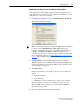
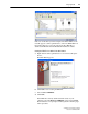
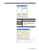
f. For the Input Size and Output Size boxes, use the pull-down menus
to choose the number of bytes that are required for your I/O.
The size will depend on the drive’s Reference/Feedback and the
number of Datalinks used in your I/O (enabled with adapter
Parameter 13 - [DPI I/O Cfg]), and the selected data exchange
method. (A 16-bit word is two bytes, and a 32-bit word is four
bytes.) For this example, an Input Size of ‘20’ and an Output Size
of ‘20’ are used.
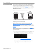
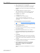
Important:Make sure that the bits for Parameters 25 - [M-S
Input] and 26 - [M-S Output] are set to match
Parameter 13 - [DPI I/O Cfg]. See Setting a
Master-Slave Hierarchy (Scanner-to-Drive
Communication) on page 3-5 for details.
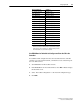
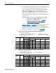
Table 4.E
, Table 4.F, or Table 4.G list the number of bytes required
for the Input Size and Output Size boxes for specific I/O
configurations—and only the Polled data exchange method. For
Input Sizes and Output Sizes for other data exchange methods and
specific I/O configurations, see the tables in Appendix
E.
Table 4.E Drives with 16-bit Reference/Feedback and 16-bit Datalinks
These products include the following:
Table 4.F Drives with 16-bit Reference/Feedback and 32-bit Datalinks
These products include the following:
• PowerFlex 70 drives with standard or enhanced control • SMC Flex smart motor controllers
• PowerFlex 700 drives with standard control • SMC-50 smart motor controllers
• PowerFlex 700H drives
Logic
Command/
Status
Ref/Fdbk
(16-bit)
Datalinks (16-bit) User Configured Settings
ABCD
Size in Bytes Par. 13 -
[DPI I/O Cfg]
Par. 25 -
[M-S Input]
Par. 26 -
[M-S Output]
Input Output
✔✔ 4 4 …0 0001 …0 0001 …0 0001
✔✔✔ 8 8 …0 0011 …0 0011 …0 0011
✔✔✔✔ 12 12 …0 0111 …0 0111 …0 0111
✔✔✔✔✔16 16 …0 1111 …0 1111 …0 1111
✔ ✔ ✔✔✔✔20 20 …1 1111 …1 1111 …1 1111
• PowerFlex 700 drives with vector control • PowerFlex Digital DC drives
• PowerFlex 700L drives with 700 control
Logic
Command/
Status
Ref/Fdbk
(16-bit)
Datalinks (32-bit) User Configured Settings
ABCD
Size in Bytes Par. 13 -
[DPI I/O Cfg]
Par. 25 -
[M-S Input]
Par. 26 -
[M-S Output]
Input Output
✔✔ 4 4 …0 0001 …0 0001 …0 0001
✔✔✔ 12 12 …0 0011 …0 0011 …0 0011
✔✔✔✔ 20 20 …0 0111 …0 0111 …0 0111
✔✔✔✔✔28 28 …0 1111 …0 1111 …0 1111
✔ ✔ ✔✔✔✔36 36 …1 1111 …1 1111 …1 1111