
Instruction Manual

E-4 Master-Slave I/O Configuration
20-COMM-D DeviceNet Adapter User Manual
Publication 20COMM-UM002G-EN-P
M-S Output Parameter
Configurations
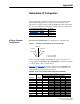
Parameter 26 - [M-S Output] has the following five configurable bits.
Figure E.2 Parameter 26 - [M-S Output] Bits and Corresponding I/O
When you enable Cmd/Ref or Datalink in the adapter, you must set the
corresponding bit in Parameter 26 - [M-S Output] if you want the output
data to be sent to the scanner or master device.
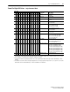
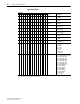
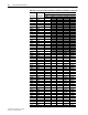
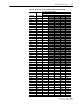
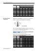
Table E.C
and Table E.D list possible configurations for Parameter 26 -
[M-S Output] and the possible data size allocation associated with each
value depending on the method of data transfer.
10100 xxxx1 16 16 16 16 and 0 16 and 0
10101 xxxx1 24 24 24 24 and 0 24 and 0
10110 xxxx1 24 24 24 24 and 0 24 and 0
10111 xxxx1 32 32 32 32 and 0 32 and 0
11000 xxxx1 16 16 16 16 and 0 16 and 0
11001 xxxx1 24 24 24 24 and 0 24 and 0
11011 xxxx1 32 32 32 32 and 0 32 and 0
11100 xxxx1 24 24 24 24 and 0 24 and 0
11101 xxxx1 32 32 32 32 and 0 32 and 0
11110 xxxx1 32 32 32 32 and 0 32 and 0
11111 xxxx1 40 40 40 40 and 0 40 and 0
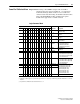
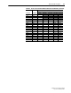
Table E.B Host Products with 32-bit Reference/Feedback and Datalinks (Continued)
M-S Input M-S Output
Allocation (Number of Bytes)
Data Size sent from the Controller to the Adapter
Poll Only COS Only Cyclic Only Poll & COS Poll & Cyclic
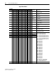
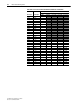
Table E.C Host Products with 16-bit Reference/Feedback and Datalinks
M-S Input M-S Output
Allocation (Number of Bytes)
Data Size sent from the Adapter to the Controller
Poll Only COS Only Cyclic Only Poll & COS Poll & Cyclic
xxxxx 00000 0
xxxxx 00010 4
xxxxx 00100 4
xxxxx 00110 8
xxxxx 01000 4
xxxxx 01010 8
xxxxx 01100 8
xxxxx 11100 12
xxxxx 10000 4
xxxxx 10010 8
xxxxx 10100 8
xxxxx 10110 12
xxx0 0000
Datalink D
Datalink C
Datalink B
Datalink A
Cmd/Ref
0 = Peer or other output
1 = Master-Slave output