
Instruction Manual

20-COMM-D DeviceNet Adapter User Manual
Publication 20COMM-UM002G-EN-P
Appendix E
Master-Slave I/O Configuration
This appendix lists possible I/O configurations with corresponding M-S
Input and M-S Output parameter settings, and the required data size
allocations for all data exchange methods except Polled. The required data
size allocation tables for the Polled data exchange method are listed below.
M-S Input Parameter
Configurations
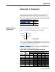
Parameter 25 - [M-S Input] has the following five configurable bits.
Figure E.1 Parameter 25 - [M-S Input] Bits and Corresponding I/O
When you enable Cmd/Ref or Datalink in the adapter, you must set the
corresponding bit in Parameter 25 - [M-S Input] if you want the input data
to come from the scanner or master device.
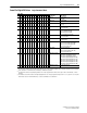
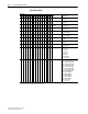
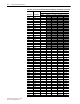
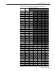
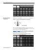
Table E.A
and Table E.B list possible configurations for Parameter 25 -
[M-S Input] and the possible data size allocation associated with each
value depending on the data exchange method.
Polled Data Exchange Method Tables Controller
Table 4.A
, Table 4. B, or Table 4.C ControlLogix
Table 4.E
, Table 4. F, or Ta ble 4.G PLC-5
Table 4.H
, Tabl e 4.I, or Table 4.J SLC 500
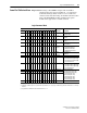
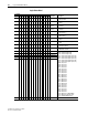
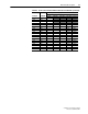
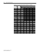
Table E.A Host Products with 16-bit Reference/Feedback and Datalinks
M-S Input M-S Output
Allocation (Number of Bytes)
Data Size sent from the Controller to the Adapter
Poll Only COS Only Cyclic Only Poll & COS Poll & Cyclic
00000 xxxx0 0
00001 xxxx0 4
00010 xxxx0 4
00011 xxxx0 8
00100 xxxx0 4
00101 xxxx0 8
00110 xxxx0 8
00111 xxxx0 12
01000 xxxx0 4
01001 xxxx0 8
01010 xxxx0 8
xxx0 0000
Datalink D
Datalink C
Datalink B
Datalink A
Cmd/Ref
0 = Peer or other input
1 = Master-Slave input