
Instruction Manual


5-42 Using the I/O
20-COMM-D DeviceNet Adapter User Manual
Publication 20COMM-UM002G-EN-P
To operate any drive and view its status using the data table addresses,
Human Machine Interface devices (PanelView, and so forth), or a ladder
logic program, you will need to create descriptive controller data table
addresses (Table 5.U
and Table 5.V) and a ladder logic program that will
pass the controller address data to the program data table addresses.
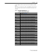
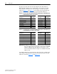
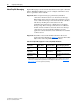
Table 5.U SLC 500 and Program Data Table Address Descriptions for Example Logic
Status/Feedback Ladder Logic Program
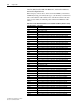
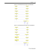
Table 5.V Program and SLC 500 Data Table Address Descriptions for Example Logic
Command/Reference Ladder Logic Program
Important: In addition to the Run mode for the processor, the scanner also
has its own Run mode. To change the scanner mode from IDLE
to RUN, set Bit 0 in data table address O:e.0, where e = the
scanner slot number. For this example, we set Bit 0 in data table
address O:1.0.
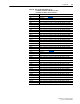
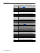
An example ladder logic program that uses these descriptive controller data
table addresses and passes their data to the descriptive program data table
addresses is shown in Figure 5.20
and Figure 5.21.
Description
SLC 500 Data
Table Address Description
Program Data
Table Address
Drive Ready N9:0/0 Status Ready B3:1/0
Drive Active N9:0/1 Status Active B3:1/1
Actual Direction (XIO) N9:0/3 Status Forward B3:1/3
Actual Direction (XIC) N9:0/3 Status Reverse B3:1/4
Drive Faulted N9:0/7 Status Faulted B3:1/7
Drive At Speed N9:0/8 Status At Speed B3:1/8
Speed Feedback N9:1 Speed Feedback N20:1
Description
Program Data
Table Address Description
SLC 500 Data
Table Address
Command Stop B3:20/0 Drive Stop N10:0/0
Command Start B3:20/1 Drive Start N10:0/1
Command Jog B3:20/2 Drive Jog N10:0/2
Command Clear Faults B3:20/3 Drive Clear Faults N10:0/3
Command Forward Reverse (XIO) B3:20/4 Drive Forward N10:0/4
Command Forward Reverse (XIC) B3:20/4 Drive Reverse N10:0/5
Speed Reference N30:1 Speed Reference N10:1