
Instruction Manual

5-36 Using the I/O
20-COMM-D DeviceNet Adapter User Manual
Publication 20COMM-UM002G-EN-P
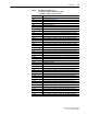
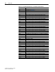
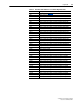
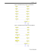
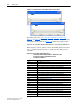
Figure 5.19 Data File Tables for Example Ladder Logic Program
Depending on the drive, Table 5.O, Table 5.P, Table 5.Q, Table 5.R,
Table 5.S
, or Table 5.T shows the I/O definitions as they relate to the N9:0
and N10:0 data table addresses (Figure 5.19
) being used in this example.
PowerFlex 70, PowerFlex 700 with Standard Control, and PowerFlex 700H Drives
When using any of these products, which contain INT (16-bit format) data
types, you will read from and write to a single data table address in the
controller.
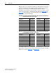
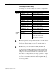
Table 5.O SLC 500 Data Table Addresses for:
PowerFlex 70 Drives with Standard or Enhanced Control
PowerFlex 700 Drives with Standard Control
PowerFlex 700H Drives
Data Table Address Description
N9:0 Logic Status (see Appendix D)
N9:1 Speed Feedback
N9:2 Value of parameter assigned to Parameter 310 [Data Out A1]
N9:3 Value of parameter assigned to Parameter 311 [Data Out A2]
N9:4 Value of parameter assigned to Parameter 312 [Data Out B1]
N9:5 Value of parameter assigned to Parameter 313 [Data Out B2]
N9:6 Value of parameter assigned to Parameter 314 [Data Out C1]
N9:7 Value of parameter assigned to Parameter 315 [Data Out C2]
N9:8 Value of parameter assigned to Parameter 316 [Data Out D1]
N9:9 Value of parameter assigned to Parameter 317 [Data Out D2]
N10:0 Logic Command (see Appendix
D)
N10:1 Speed Reference
N10:2 Value of parameter assigned to Parameter 300 [Data In A1]
N10:3 Value of parameter assigned to Parameter 301 [Data In A2]
N10:4 Value of parameter assigned to Parameter 302 [Data In B1]
N10:5 Value of parameter assigned to Parameter 303 [Data In B2]
N10:6 Value of parameter assigned to Parameter 304 [Data In C1]
N10:7 Value of parameter assigned to Parameter 305 [Data In C2]
N10:8 Value of parameter assigned to Parameter 306 [Data In D1]
N10:9 Value of parameter assigned to Parameter 307 [Data In D2]