
Instruction Manual

Using the I/O 5-17
20-COMM-D DeviceNet Adapter User Manual
Publication 20COMM-UM002G-EN-P
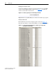
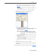
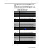
An example ladder logic program that uses the automatically-created
descriptive Controller tags and passes their data to the user-defined Program
tags is shown in Figure 5.10
and Figure 5.11. Note that the prefix for the
drive Controller tags is determined by the name assigned when configuring
the I/O (Chapter 4
).
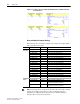
Figure 5.10 ControlLogix Example Ladder Logic Program with Descriptive Controller
Tags for Logic Status/Feedback
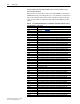
Figure 5.11 ControlLogix Example Ladder Logic Program with Descriptive Controller
Tags for Logic Command/Reference