BACnet MS/TP Adapter 20-COMM-B FRN 1.
Important User Information Solid state equipment has operational characteristics differing from those of electromechanical equipment. Safety Guidelines for the Application, Installation and Maintenance of Solid State Controls (Publication SGI-1.1 available from your local Rockwell Automation sales office or online at http://www.rockwellautomation.com/ literature) describes some important differences between solid state equipment and hard-wired electromechanical devices.
Summary of Changes The information below summarizes the changes made to this manual since its last release (May 2006): Description of Changes In the “Quick Start” section: • In Step 4, removed connecting the adapter to the network. • In Step 5, added two new sub-steps (B and C). • Added a new Step 6 “Connect the adapter to the network.” • Incremented old Steps 6 and 7 to Steps 7 to 8.
soc-ii Summary of Changes
Table of Contents Preface About This Manual Related Documentation . . . . . . . . . . . . . . . . . . . . . . . . . . . . . P-1 Rockwell Automation Support. . . . . . . . . . . . . . . . . . . . . . . . P-2 Conventions Used in This Manual . . . . . . . . . . . . . . . . . . . . . P-2 Chapter 1 Getting Started Components . . . . . . . . . . . . . . . . . . . . . . . . . . . . . . . . . . . . . . Features . . . . . . . . . . . . . . . . . . . . . . . . . . . . . . . . . . . . . . . . .
ii Table of Contents Chapter 5 Troubleshooting Understanding the Status Indicators . . . . . . . . . . . . . . . . . . . PORT Status Indicator . . . . . . . . . . . . . . . . . . . . . . . . . . . . . . MOD Status Indicator . . . . . . . . . . . . . . . . . . . . . . . . . . . . . . NET A Status Indicator . . . . . . . . . . . . . . . . . . . . . . . . . . . . . NET B Status Indicator . . . . . . . . . . . . . . . . . . . . . . . . . . . . . Viewing and Clearing Adapter Diagnostic Items. . . . . . . . .
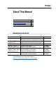
Preface About This Manual Topic Related Documentation Rockwell Automation Support Conventions Used in This Manual Page P-1 P-2 P-2 Related Documentation For: DriveExplorer™ Refer to: Publication http://www.ab.com/drives/driveexplorer, and — DriveExplorer online help (installed with the software) — DriveTools™ SP (includes http://www.ab.
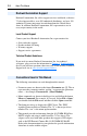
P-2 About This Manual Rockwell Automation Support Rockwell Automation, Inc. offers support services worldwide, with over 75 sales/support offices, over 500 authorized distributors, and over 250 authorized systems integrators located throughout the United States alone. In addition, Rockwell Automation, Inc. representatives are in every major country in the world. Local Product Support Contact your local Rockwell Automation, Inc.
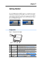
Chapter 1 Getting Started The 20-COMM-B BACnet MS/TP adapter is a communication option intended for installation into a PowerFlex 7-Class drive. It can also be used with other Allen-Bradley products that support an internal DPI ™ (Drive Peripheral Interface) adapter, such as the DPI External Comms Kit (20-XCOMM-DC-BASE). Topic Components Features Compatible Products Required Equipment Page 1-1 1-2 1-3 1-3 Topic Safety Precautions Quick Start Status Indicators Page 1-4 1-6 1-7 Components Figure 1.
1-2 Getting Started Features The 20-COMM-B BACnet MS/TP adapter features the following: • The adapter is normally mounted in the PowerFlex 7-Class drive. It can also be installed in a DPI External Comms Kit Important: Due to inherent operating limitations, the adapter cannot be used with the kit’s optional I/O board. • Switches let you: – Set a MAC address before applying power to the drive.
Getting Started 1-3 Compatible Products The 20-COMM-B BACnet MS/TP adapter is compatible with most Allen-Bradley PowerFlex 7-Class (Architecture-Class) drives and other products that support DPI. DPI is a second generation peripheral communication interface and functional enhancement to SCANport.
1-4 Getting Started Safety Precautions Please read the following safety precautions carefully. ! ! ! ! ! ! ATTENTION: Risk of injury or death exists. The PowerFlex drive may contain high voltages that can cause injury or death. Remove power from the PowerFlex drive, and then verify power has been discharged before installing or removing an adapter. ATTENTION: Risk of injury or equipment damage exists.
Getting Started ! ! 1-5 ATTENTION: Risk of injury or equipment damage exists. Parameter 03 - [Comm Loss Time] lets you determine how long it will take the adapter to detect network communication losses. By default, this parameter sets the timeout to ten seconds. You can set it so that the duration is shorter, longer, or disabled. When set to disabled, this also disables adapter Parameter 02 - [Comm Loss Action]. Therefore, a communications fault action will be ignored.
1-6 Getting Started Quick Start This section is provided to help experienced users quickly start using the adapter. If you are unsure how to complete a step, refer to the referenced chapter. Step 1 2 3 4 5 Action Review the safety precautions for the adapter. Verify that the PowerFlex drive is properly installed. Commission the adapter.
Getting Started 1-7 Status Indicators The adapter uses four status indicators to report its operating status. They can be viewed on the adapter or through the drive cover (Figure 1.2). Figure 1.
1-8 Notes: Getting Started
Chapter 2 Installing the Adapter Chapter 2 provides instructions for installing the adapter in a PowerFlex 7-Class drive. This adapter can also be installed in a DPI External Comms Kit. In this case, refer to the 20-XCOMM-DC-BASE Installation Instructions (Publication No. 20COMM-IN001…) supplied with the kit.
2-2 Installing the Adapter Setting the MAC Address Set the MAC address using the MAC Address switches (Figure 2.1). Refer to Table 2.A for specific MAC address switch settings. Important: Each node on the network must have a unique MAC address. The MAC address must be set before power is applied because the adapter uses the MAC address it detects when it first receives power. To change a MAC address, you must set the new value. Then remove and reapply power to the adapter, or reset the adapter. Figure 2.
Installing the Adapter 2-3 Table 2.
2-4 Installing the Adapter Table 2.
Installing the Adapter 2-5 Network with PowerFlex Drives at Starting and/or Ending Nodes For a network with PowerFlex drives at the starting and/or ending nodes (Figure 2.3), set their 20-COMM-B adapter’s TERM, -BIAS, and +BIAS switches to the “Down” (On) position. All other PowerFlex drive network nodes must have these switches set to the “Up” (Off) position. Figure 2.
2-6 Installing the Adapter Connecting the Adapter to the Drive 1. Remove power from the drive. 2. Use static control precautions, and remove or open the drive cover. 3. Connect the Internal Interface cable to the DPI port on the drive and then to the DPI connector on the adapter. Figure 2.5 DPI Ports and Internal Interface Cables ➊ 20-COMM-B Adapter ➋ ➌ PowerFlex 70 Drive ➍ PowerFlex 700 Drive Frames 0 - 1 PowerFlex 700 Drive Frames 2 and Larger Item Description ➊ 15.24 cm (6 in.
Installing the Adapter 2-7 4. Secure and ground the adapter to the drive by doing the following: – On a PowerFlex 70 drive, fold the Internal Interface cable behind the adapter and mount the adapter on the drive using the four captive screws. – On a PowerFlex 700 or PowerFlex 700H drive, just mount the adapter on the drive using the four captive screws. Important: Tighten all screws since the adapter is grounded via the screws. Recommended torque is 0.9 N-m (8.0 lb.-in.). Figure 2.
2-8 Installing the Adapter Applying Power ! ATTENTION: Risk of equipment damage, injury, or death exists. Unpredictable operation may occur if you fail to verify that parameter settings are compatible with your application. Verify that settings are compatible with your application before applying power to the drive. Install or close the drive cover, and apply power to the drive. The adapter receives its power from the connected drive.
Installing the Adapter 2-9 Table 2.B Drive and Adapter Start-Up Status Indications Item Name Color ➊ STS Green (Status) Yellow Red ➋ PORT Green MOD Green NET A Green NET B Green State Description Drive STS Indicator Flashing Drive ready but not running, and no faults are present. Steady Drive running, no faults are present. Flashing, An inhibit condition exists – the drive cannot be started. Drive Stopped Check drive Parameter 214 - [Start Inhibits].
2-10 Installing the Adapter Configuring/Verifying Key Drive Parameters The PowerFlex 7-Class drive can be separately configured for the control and reference functions in various combinations. For example, you could set the drive to have its control come from a peripheral or terminal block with the reference coming from the BACnet MS/TP network. Or you could set the drive to have its control come from the BACnet MS/TP network with the reference coming from another peripheral or terminal block.
Installing the Adapter 2-11 Figure 2.8 Typical Network Terminal Connections Terminal SHLD +B -A Node "n" Signal Termination Signal B Signal A -A LD +B SH -A +B LD Node 2 SH -A +B SH LD Node 1 Function Shield Termination TxRxD+ TxRxD- 5. Insert the 3-pin linear plug into the mating adapter socket. 6. Install or close the drive cover. 7. Apply power to the drive. 8. Verify that adapter Parameter 07 - [Baud Rate Act] is reporting the actual network baud rate.
2-12 Notes: Installing the Adapter
Chapter 3 Configuring the Adapter Chapter 3 provides instructions and information for setting the parameters in the adapter. Topic Configuration Tools Using the PowerFlex 7-Class HIM Setting the Device Instance Number Setting a Comm Loss Action Setting the Comm Loss Time Setting the Baud Rate Resetting the Adapter Viewing the Adapter Configuration Page 3-1 3-2 3-3 3-5 3-6 3-7 3-7 3-8 For a list of parameters, refer to Appendix B, Adapter Parameters.
3-2 Configuring the Adapter Using the PowerFlex 7-Class HIM If your drive has either an LED or LCD HIM (Human Interface Module), you can use it to access parameters in the adapter as shown below. It is recommended that you read through the steps for your HIM before performing the sequence. For additional HIM information, refer to your PowerFlex Drive User Manual or the HIM Quick Reference card. Using an LED HIM Step Key(s) Example Screens 1.
Configuring the Adapter 3-3 Setting the Device Instance Number While there are many ways to implement Device Instance and network strategies, the example shown in Figure 3.1 illustrates one logical approach. In this example, two individual Floor Level Networks are connected to the Building Level Network through a router which allows devices on each network to share the same MAC address. However, each device on the network must have a unique Device Instance which, in this case, consists of 4 digits.
3-4 Configuring the Adapter 1. Set the value of Parameter 11 - [Device Instance] to a unique Device Instance Number. Figure 3.2 Device Instance Screen on an LCD HIM Port 5 Device Default = 160000 20-COMM-B Parameter #: 11 Device Instance 160000 2. Reset the adapter (see Resetting the Adapter on page 3-7) so that the new Device Instance Number takes effect.
Configuring the Adapter 3-5 Setting a Comm Loss Action By default, when communications are disrupted (for example, a cable is disconnected), the drive responds by faulting if it is using I/O from the network. You can configure a different response to communication disruptions using Parameter 02 - [Comm Loss Action]. ! ATTENTION: Risk of injury or equipment damage exists. Parameter 02 - [Comm Loss Action] lets you determine the action of the adapter and connected drive if communications are disrupted.
3-6 Configuring the Adapter To set the fault configuration parameters If you set Parameter 02 - [Comm Loss Action] to “Send Flt Cfg,” the values in the following parameters are sent to the drive after a communications fault occurs. You must set these parameters to values required by your application. Parameter 04 05 Name Flt Cfg Logic Flt Cfg Ref Description A 16-bit value sent to the drive for Logic Command. A 32-bit value (0 – 4294967295) sent to the drive as a Reference.
Configuring the Adapter 3-7 Setting the Baud Rate The value of Parameter 06 - [Baud Rate Cfg] determines the baud rate used by the adapter. The Autobaud setting will detect the baud rate used on the network if another device is setting the baud rate. Your application may require a different setting. 1. Set the value of Parameter 06 - [Baud Rate Cfg] to the baud rate at which your network is operating. Figure 3.
3-8 Configuring the Adapter When you enter 1 = Reset Module, the adapter will be immediately reset. When you enter 2 = Set Defaults, the adapter will set all adapter parameters to their factory-default settings. After performing a Set Defaults, enter 1 = Reset Module so that the new values take effect. The value of this parameter will be restored to 0 = Ready after the adapter is reset.
Chapter 4 Using BACnet Objects Chapter 4 provides information about controlling a compatible PowerFlex 7-Class drive using BACnet objects. Topic Understanding BACnet Objects Basic Drive Operation on the Network Supported BACnet Objects Page 4-1 4-2 4-3 Understanding BACnet Objects BACnet nodes are controlled and monitored by the use of several types of objects.
4-2 Using BACnet Objects Basic Drive Operation on the Network This section describes how to operate a drive on the network using a combination of BACnet object types for basic control. ! ATTENTION: Control information written to the adapter by a BACnet controller is volatile. That is, it will not survive an adapter reset or power cycle.
AV2 AV3 AV0 AV1 AO1 AO0 AI1 AI0 Use This Object to… Analog Input 1 (%) Analog Input (AI) Objects Read the value of Analog Input 1 (voltage or current) on the drive’s I/O terminal block. Analog Input 2 (%) Read the value of Analog Input 2 (voltage or current) on the drive’s I/O terminal block. Analog Output (AO) Objects Analog Output 1 (%) Read/write the value of Analog Output 1 on the drive’s I/O terminal block. The drive must be configured to accept the value of this output from the network.
BI0 BI1 BI2 AV12 AV13 AV14 AV15 AV16 AV17 AV18 AV7 AV8 AV9 AV10 AV11 AV4 AV5 AV6 Use This Object to… Read the drive’s output voltage. Read the drive’s output power. Read/write the drive’s accumulated output energy. Note: When writing, this object accepts only a value of “0” (zero). DC Bus Voltage (VDC) Read the drive’s DC bus voltage. Drive Temp (°C) Read the drive’s temperature. PID Feedback (%) Read the drive’s PID feedback. PID Error (%) Read the drive’s PID error.
Use This Object to… Read the state of Digital Input 4 on the drive’s I/O terminal block. Read the state of Digital Input 5 on the drive’s I/O terminal block. Read the state of Digital Input 6 on the drive’s I/O terminal block. Read the state of Digital Output 1 on the drive’s I/O terminal block. Read the state of Digital Output 2 on the drive’s I/O terminal block. Read the state of Digital Output 3 on the drive’s I/O terminal block.
Running Reverse Fault Alarm At Reference Run/Stop Rev/Fwd Ref2/Ref1 Clear Faults BV2 BV3 BV4 BV5 BV10 BV11 BV12 BV13 Object Name Use This Object to… Compatible PowerFlex Drives 70 Std. 70 EC 700 Std. 700 VC 700 H Read the drive’s Running Reverse status, which is active if the drive is ✔ ✔ ✔ ✔ ✔ running in the reverse direction. Read the drive’s Fault status, which is active if the drive is faulted. ✔ ✔ ✔ ✔ ✔ Read the drive’s Alarm status, which is active if the drive has an ✔ ✔ ✔ ✔ ✔ alarm.
Chapter 5 Troubleshooting Chapter 5 provides information for diagnosing and troubleshooting potential problems with the adapter and network. Topic Understanding the Status Indicators PORT Status Indicator MOD Status Indicator NET A Status Indicator NET B Status Indicator Viewing and Clearing Adapter Diagnostic Items Viewing and Clearing Events Page 5-1 5-2 5-3 5-4 5-4 5-5 5-7 Understanding the Status Indicators The adapter has four status indicators.
5-2 Troubleshooting PORT Status Indicator State Off Flashing Red Solid Red Cause Corrective Actions The adapter is not powered or • Securely connect the adapter to the drive is not properly connected to using the Internal Interface (ribbon) the drive. cable. • Apply power to the drive (or adapter if mounted in a DPI External Comms Kit). The adapter is not receiving a • Verify that cables are securely connected ping message from the drive. and not damaged. Replace cables if necessary.
Troubleshooting 5-3 MOD Status Indicator State Off Flashing Red Cause Corrective Actions The adapter is not powered or • Securely connect the adapter to the drive is not properly connected to using the Internal Interface (ribbon) the drive. cable. The adapter has failed the firmware test. • Apply power to the drive (or adapter if mounted in a DPI External Comms Kit). • Cycle power to the drive (or adapter if mounted in a DPI External Comms Kit).
5-4 Troubleshooting NET A Status Indicator State Off Flashing Red Flashing Green Cause Corrective Actions The adapter is not powered or • Securely connect the adapter to the drive is not properly connected to using the Internal Interface (ribbon) cable. the network. • Correctly connect the network cable to the adapter’s network connector. A network connection has timed out. • Apply power to the drive (or adapter if mounted in a DPI External Comms Kit) and network.
Troubleshooting 5-5 Viewing and Clearing Adapter Diagnostic Items The following adapter diagnostic items can be viewed using DriveExplorer (version 3.01 or higher) or DriveExecutive (version 3.01 or higher) software, or an LCD PowerFlex HIM (Diagnostic/Device Items). To view and clear adapter diagnostic items Step Viewing Diagnostic Items Keys Example Screen 1. Access parameters in the adapter. Refer to Using the PowerFlex 7-Class HIM on page 3-2. 2.
5-6 Troubleshooting Adapter Diagnostic Items If you encounter unexpected communications problems, diagnostic items can help you or Rockwell Automation personnel troubleshoot the problem. No. Name 1 Common Logic Cmd 2 Prod Logic Cmd 3 4 5 6 7 8 9 10 11 12 13 14 15 16 17 18 19 20 21 Description The present value of the Common Logic Command being transmitted to the drive by this adapter. The present value of the Product Logic Command being transmitted to the drive by this adapter.
Troubleshooting 5-7 Viewing and Clearing Events The adapter maintains an event queue that reports the history of its actions. You can view this event queue using an LCD PowerFlex HIM, DriveExplorer software (3.01 or higher), or DriveExecutive software (3.01 or higher). To view and clear events Step Viewing Events Keys Example Screen 1. Access parameters in the adapter. Refer to Using the PowerFlex 7-Class HIM on page 3-2. 2. Press the Up Arrow or Down Arrow to scroll to Diagnostics.
5-8 Troubleshooting Events Many events in the Event queue occur under normal operation. If you encounter unexpected communications problems, the events may help you or Allen-Bradley personnel troubleshoot the problem. The following events may appear in the event queue: Code Event 1 No Event 2 DPI Bus Off Flt 3 4 5 6 7 8 9 10 11 12 13 14 15 16 17 18 19 20 21 22 23 24 25 26 27 28 29 30 31 32 33 34 35 Description Empty event queue entry. A bus-off condition was detected on DPI.
Appendix A Specifications Appendix A presents the specifications for the adapter. Topic Communications Electrical Mechanical Environmental Regulatory Compliance Page A-1 A-1 A-1 A-2 A-2 Communications Network Protocols Data Rates Drive Protocol Data Rates BACnet MS/TP 9600, 19200, 38400 or 76800 baud DPI 125 kbps or 500 kbps Electrical Consumption Drive Network 150 mA at 5 VDC None Mechanical Dimensions Height Length Width Weight 19 mm (0.75 in.) 86 mm (3.39 in.) 78.5 mm (3.09 in.) 85g (3 oz.
A-2 Specifications Environmental Temperature Operating Storage Relative Humidity Atmosphere -10 to 50°C (14 to 122°F) -40 to 85°C (-40 to 185°F) 5 to 95% non-condensing Important: The adapter must not be installed in an area where the ambient atmosphere contains volatile or corrosive gas, vapors or dust. If the adapter is not going to be installed for a period of time, it must be stored in an area where it will not be exposed to a corrosive atmosphere.
Appendix B Adapter Parameters Appendix B provides information about the BACnet MS/TP adapter parameters. Topic About Parameter Numbers Parameter List Page B-1 B-1 About Parameter Numbers The parameters in the adapter are numbered consecutively. However, depending on which configuration tool you use, they may have different numbers. Configuration Tool • DriveExplorer • DriveExecutive • HIM Numbering Scheme The adapter parameters begin with parameter 1.
B-2 Adapter Parameters Parameter No. Name and Description Details 02 [Comm Loss Action] Default: Sets the action that the adapter and drive will take Values: if the adapter detects that network communications have been disrupted. This setting is effective only if I/O that controls the drive is transmitted through the adapter. Type: Reset Required: ! 03 04 05 06 ATTENTION: Risk of injury or equipment damage exists.
Adapter Parameters Parameter No. Name and Description 07 [Baud Rate Act] Displays the baud rate (kilobits per second) actually used by the adapter. 08 09 [MAC Address] Displays the actual address selected by the MAC Address Switches SW1-SW7 (Figure 2.1) on the adapter. This value is latched when the adapter powers up. [Max Master] Sets the maximum MAC Address for any device in the BACnet MS/TP token ring.
B-4 Notes: Adapter Parameters
Appendix C Protocol Implementation Conformance Statement (PICS) Date: March 27, 2006 Vendor Name: Rockwell Automation Product Name: 20-COMM-B Product Model Number: 20-COMM-B Applications Software Version: 3.003 Firmware Revision: 1.
C-2 Protocol Implementation Conformance Statement (PICS) Standard Object Types Supported The table below lists the object types supported by the 20-COMM-B. Dynamic object creation and deletion is not supported.
Protocol Implementation Conformance Statement (PICS) C-3 Data Link Layer Options BACnet IP, (Annex J) BACnet IP, (Annex J), Foreign Device ISO 8802-3, Ethernet (Clause 7) ANSI/ATA 878.1, 2.5 Mb. ARCNET (Clause 8) ANSI/ATA 878.
C-4 Notes: Protocol Implementation Conformance Statement (PICS)
Appendix D Routing Capability for Networked Drives Appendix D provides information about the unique routing capability for up to 127 PowerFlex 7-Class drives on a BACnet MS/TP network when using the DriveExplorer (Full version only) drive software tool. First, configure the 20-COMM-B adapter in each networked drive using the procedures described in Chapter 2. Then use a 1203-USB or 1203-SSS converter to connect the first networked drive to a laptop or desktop PC with DriveExplorer Full.
D-2 Notes: Routing Capability for Networked Drives
Glossary A Adapter Devices such as drives, controllers, and computers usually require an adapter to provide a communication interface between them and a network such as BACnet MS/TP. An adapter reads data on the network and transmits it to the connected device. It also reads data in the device and transmits it to the network. The 20-COMM-B adapter connects PowerFlex 7-Class drives to a BACnet MS/TP network.
Glossary-2 DPI Peripheral A device that provides an interface between DPI and a network or user. Peripheral devices are also referred to as “adapters” and “modules.” The 20-COMM-B, 1203-SSS or 1203-USB converter, and PowerFlex 7-Class HIMs (20-HIM-xxx) are examples of DPI peripherals. DPI Product A device that uses the DPI communications interface to communicate with one or more peripheral devices. For example, a motor drive such as a PowerFlex 7-Class drive is a DPI product.
Glossary-3 user-defined fault configuration. The user sets the data that is sent to the drive using specific fault configuration parameters in the adapter. When a fault action parameter is set to use the fault configuration data and a fault occurs, the data from these parameters is sent as the Logic Command and Reference. Flash Update The process of updating firmware in a device.
Glossary-4 from the adapter to the network. The definitions of the bits in this word depend on the drive. M MAC Address Each device on a network must have a unique MAC address to identify it. On BACnet MS/TP networks, devices can have MAC addresses between 0 and 127 if the network is set up to accommodate that number of devices. N NVS (Non-Volatile Storage) NVS is the permanent memory of a device.
Glossary-5 S Status Indicators Status indicators are LEDs that are used to report the status of the adapter, network, and drive. They are on the adapter and can be viewed on the front cover of the drive when the drive is powered. T Type 0 Control When transmitting I/O, the adapter can use different types of messages for control. The Type 0 events help Allen-Bradley personnel identify the type of messages that an adapter is using.
Glossary-6
Index Numerics 3-pin linear plug, 2-11 A adapter applying power, 2-8 commissioning, 2-1 compatible products, 1-3 components, 1-1 connecting to a drive, 2-6 connecting to the network, 2-10 definition, G-1 features, 1-2 grounding, 2-7 installation, 2-1 to 2-11 mounting on a drive, 2-7 parameters, B-1 to B-3 resetting, 3-7 setting the baud rate, 3-7 setting the MAC address, 2-2 specifications, A-1 viewing its configuration, 3-8 applying power to the adapter, 2-8 attentions, 1-4 B BACnet MS/TP network, G-1 BA
Index-2 E EDS (Electronic Data Sheet) files definition, G-2 web site, G-2 EEPROM, see Non-Volatile Storage (NVS) electrical specifications, A-1 environmental specifications, A-2 equipment required, 1-3 events list of, 5-8 viewing and clearing, 5-7 I I/O data, G-3 installation applying power to the adapter, 2-8 connecting to the drive, 2-6 connecting to the network, 2-10 preparing for, 2-1 Internal Interface cables connecting to adapter and drive, 2-6 shipped with adapter, 1-3 L F factory-default settings
Index-3 NET B status indicator locating, 1-7 troubleshooting with, 5-4 network cable - connecting to 3-pin plug, 2-11 Non-Volatile Storage (NVS) accessing parameters in, 3-1 definition, G-4 P parameters accessing, 3-1 configuring, 3-1 to 3-8 list of, B-1 to B-3 numbering scheme, B-1 restoring to factory-default settings, 3-7 PCCC (Programmable Controller Communications Command), G-4 ping, G-4 plug for network cable, 2-11 PORT status indicator locating, 1-7 troubleshooting with, 5-2 power consumption, A-1 P
Index-4 W web site DriveExecutive software, G-2 DriveExplorer software, G-2 DriveTools SP software, G-2 EDS files, G-2 PowerFlex manuals, P-1 Z zero data configuring the adapter for, 3-5 definition, G-5
Index-5 Notes:
Index-6 Notes:
U.S. Allen-Bradley Drives Technical Support Tel: (1) 262.512.8176, Fax: (1) 262.512.2222, Email: support@drives.ra.rockwell.com, Online: www.ab.com/support/abdrives www.rockwellautomation.com Power, Control and Information Solutions Headquarters Americas: Rockwell Automation, 1201 South Second Street, Milwaukee, WI 53204-2496 USA,Tel: (1) 414.382.2000, Fax: (1) 414.382.