User Manual PowerFlex 20-750-PBUS Profibus DPV1 Option Module FRN 1.
Important User Information Solid-state equipment has operational characteristics differing from those of electromechanical equipment. Safety Guidelines for the Application, Installation and Maintenance of Solid State Controls (publication SGI-1.1 available from your local Rockwell Automation sales office or online at http://www.rockwellautomation.com/literature/) describes some important differences between solid-state equipment and hard-wired electromechanical devices.
Summary of Changes This manual contains new and updated information. New and Updated Information This table contains the changes made to this revision. Topic Page Added information about the Connected Components Workbench software tool. Throughout manual Added Important statement about the larger T15 Torx head mounting screw to step 3 in the ‘Quick Start’ table. 17 Updated option module mounting information in the section ‘Connecting Option Module to the Drive’.
Summary of Changes Notes: 4 Rockwell Automation Publication 750COM-UM004B-EN-P - September 2012
Table of Contents Preface Conventions Used in This Manual . . . . . . . . . . . . . . . . . . . . . . . . . . . . . . . . . 9 Rockwell Automation Support . . . . . . . . . . . . . . . . . . . . . . . . . . . . . . . . . . . . . 9 Additional Resources . . . . . . . . . . . . . . . . . . . . . . . . . . . . . . . . . . . . . . . . . . . . . 10 Chapter 1 Getting Started Components. . . . . . . . . . . . . . . . . . . . . . . . . . . . . . . . . . . . . . . . . . . . . . . . . . . . . Features . . . . . . .
Table of Contents Chapter 5 Using the I/O About I/O Messaging. . . . . . . . . . . . . . . . . . . . . . . . . . . . . . . . . . . . . . . . . . . . . Understanding the I/O Image . . . . . . . . . . . . . . . . . . . . . . . . . . . . . . . . . . . . . Using Logic Command/Status . . . . . . . . . . . . . . . . . . . . . . . . . . . . . . . . . . . . Using Reference/Feedback . . . . . . . . . . . . . . . . . . . . . . . . . . . . . . . . . . . . . . . . Using Datalinks . . . . . . . . . . . . . . . . . . .
Table of Contents Glossary Index Rockwell Automation Publication 750COM-UM004B-EN-P - September 2012 7
Table of Contents Notes: 8 Rockwell Automation Publication 750COM-UM004B-EN-P - September 2012
Preface This manual provides information about the 20-750-PBUS Profibus DPV1 option module for network communications option and how to use the module with PowerFlex® 750-Series drives. Conventions Used in This Manual The following conventions are used throughout this manual: • Parameter names are shown in the format Device Parameter xx - [*] or Host Parameter xx - [*]. The xx represents the parameter number. The * represents the parameter name—for example Device Parameter 01 - [DPI Port].
Preface Additional Resources These documents contain additional information concerning related products from Rockwell Automation and others. Resource Description Network Communication Option Module Installation Instructions, publication 750COM-IN002 Information on the installation of PowerFlex 750-Series Network Communication Modules. Profibus Installation Guideline at http://www.profibus.com/ Information on the planning, installation, and techniques used to implement a Profibus network.
Chapter 1 Getting Started The 20-750-PBUS option module is intended for installation into a PowerFlex 750-Series drive and is used for network communication. Topic Page Components 11 Features 12 Understanding Parameter Types 13 Compatible Products 13 Required Equipment 13 Safety Precautions 16 Quick Start 17 Components ➊ ➋ ➌ Item Part Description ➊ Status Indicators Three status indicators that indicate the status of the option module and network communication.
Chapter 1 Features Getting Started The features of the option module include the following: • Captive screws to secure and ground the option module to the drive. • Switches to set a node address before applying power to the drive—or you can disable the switches and use an option module parameter to configure the node address.
Getting Started Understanding Parameter Types Chapter 1 The option module has two types of parameters: • Device parameters are used to configure the option module to operate on the network. • Host parameters are used to configure the option module Datalink transfer and various fault actions with the drive.
Chapter 1 Getting Started User-Supplied Equipment To install and configure the option module, you must supply the following: ❑ A small screwdriver ❑ Profibus cable; only use cable that conforms to Profibus cable standards (Belden #3079A Profibus cable or equivalent is recommended) ❑ One 9-pin, male D-Sub Profibus connector Profibus connectors are available from a variety of sources and in various sizes. As such, there may be mechanical limitations that prohibit the use of some connectors.
Getting Started Chapter 1 – DriveExecutive software, version 5.01 or later A Lite version of DriveExecutive software ships with RSLogix 5000, RSNetworx MD, FactoryTalk AssetCentre, and IntelliCENTER software.
Chapter 1 Getting Started Safety Precautions Please read the following safety precautions carefully. ATTENTION: Risk of injury or death exists. The PowerFlex drive may contain high voltages that can cause injury or death. Remove all power from the PowerFlex drive, and then verify power has been discharged before installing or removing the option module. ATTENTION: Risk of injury or equipment damage exists.
Getting Started Quick Start Chapter 1 This section is provided to help experienced users quickly start using the Option Module. If you are unsure how to complete a step, refer to the referenced chapter. Step Action See 1 Review the safety precautions for the option module. Throughout this manual 2 Verify that the PowerFlex drive is properly installed. PowerFlex 750-Series AC Drive Installation Instructions, publication 750-IN001 3 Install the option module.
Chapter 1 Getting Started Notes: 18 Rockwell Automation Publication 750COM-UM004B-EN-P - September 2012
Chapter 2 Installing the Option Module This chapter provides instructions for installing the option module in a PowerFlex 750-Series drive.
Chapter 2 Installing the Option Module Setting the Endianness and Node Address Switches Set the Endianness of the option module with Byte Swap switch 8 (see Figure 1). The Byte Swap switch can be set to either open ‘0’ (Little Endian) or closed ‘1’ (Big Endian) data formats for the cyclic data exchanged on the network.
Installing the Option Module Chapter 2 Node Address Switch 1 Node Address 7 6 5 4 3 2 1 0 0 14 0 0 0 1 1 1 0 0 1 15 0 0 0 1 1 1 1 0 1 0 16 0 0 1 0 0 0 0 0 0 1 1 17 0 0 1 0 0 0 1 0 0 1 0 0 18 0 0 1 0 0 1 0 0 0 1 0 1 19 0 0 1 0 0 1 1 0 0 0 1 1 0 20 0 0 1 0 1 0 0 0 0 0 0 1 1 1 … Table 1 - Node Address Switch Settings Node Address Switch 08 0 0 0 1 0 0 0 120 1 1 1 1 0 0 0 09 0 0 0 1 0 0
Chapter 2 Installing the Option Module Connecting the Option Module to the Drive IMPORTANT Remove power from the drive before installing the option module in the drive control pod. 1. Insert the option module into Port 4, 5, or 6 and tighten the module mounting screws into the pod mounting bracket. To properly ground the module to the drive, torque both mounting screws to 0.45…0.67 N•m (4.0…6.0 lb•in). 2.
Installing the Option Module Connecting the Option Module to the Network Chapter 2 ATTENTION: Risk of injury or death exists. The PowerFlex drive may contain high voltages that can cause injury or death. Remove power from the drive, and then verify power has been discharged before connecting the option module to the network. 1. Remove power from the drive. 2. Remove the drive cover and lift up the drive HIM bezel to its open position to access the drive control pod. 3. Use static control precautions. 4.
Chapter 2 Installing the Option Module Terminal Signal Function Housing Shield Bus cable shield (outer screen that surrounds A and B conductors) 1 Not connected — 2 Not connected — 3 B-LINE Positive RxD/TxD, according to RS485 specification 4 RTS Request to send 5 GND BUS Network Zero Volt Reference (isolated from drive side) 6 +5V BUS +5V output to network (isolated from drive side) 7 Not connected — 8 A-LINE Negative RxD/TxD according to RS485 specification 9 Not connected
Installing the Option Module Applying Power Chapter 2 ATTENTION: Risk of equipment damage, injury, or death exists. Unpredictable operation may occur if you fail to verify that parameter settings are compatible with your application. Verify that settings are compatible with your application before applying power to the drive. Apply power to the drive. The option module receives its power from the drive.
Chapter 2 Installing the Option Module Table 2 - Drive and Option Module Start-Up Status Indications Item Name Color State Description Drive STS Indicator ➊ STS Green (Status) Yellow Red Flashing Drive ready but not running, and no faults are present. Steady Drive running, no faults are present. Flashing When running, a type 2 (non-configurable) alarm condition exists – drive continues to run.
Installing the Option Module Chapter 2 Configuring and Verifying Key Drive Parameters The PowerFlex 750-Series drive can be separately configured for the control and Reference functions in various combinations. For example, you could set the drive to receive control commands from a peripheral or terminal block, with the Reference coming from the network. You could also set the drive to receive its control from the network with the Reference coming from another peripheral or terminal block.
Chapter 2 Installing the Option Module problem occurs, this verification step provides the diagnostic capability to determine whether the drive/option module or the network is the cause. 4. If hard-wired discrete digital inputs are not used to control the drive, verify that all unused digital input drive parameters are set to ‘0’ (Not Used).
Chapter 3 Configuring the Option Module This chapter provides instructions and information for setting the parameters to configure the option module.
Chapter 3 Configuring the Option Module Using the PowerFlex 20HIM-A6 or 20-HIM-C6S HIM to Access Parameters If your drive has an enhanced PowerFlex 20-HIM-A6 or 20-HIM-C6S HIM, it can be used to access parameters in the option module. 1. Display the Status screen, which is shown on HIM powerup. 2. Use the or module is installed. key to scroll to the Port in which the option 3. Press the PAR# soft key to display the Jump to Param # entry pop-up box. 4.
Configuring the Option Module Chapter 3 Parameters 01 - [DL From Net 01] through 16 - [DL From Net 16]. The data type of a Datalink can be either a 32-bit REAL (floating point) or 32-bit integer. The number of Datalinks actively used is controlled by the connection size configured in the controller. See the controller example sections in Chapter 4 for more information on setting the connection size.
Chapter 3 Configuring the Option Module After the above steps are complete, the option module is ready to receive input data and transfer status data to the Profibus master (controller). Next, configure the controller to recognize and transmit I/O to the option module. See Chapter 4, Configuring the Profibus Master. Enable Datalinks To Read Data The controller input image (drive-to-controller inputs) can have 0 to 16 additional 32-bit parameters (Datalinks).
Configuring the Option Module Setting a Fault Action Chapter 3 By default, when communication is disrupted (for example, the network cable is disconnected) or the master (controller) is idle, the drive responds by faulting if it is using I/O from the network. You can configure a different response to these events: • Disrupted I/O communication by using Host Parameter 33 - [Comm Flt Action]. • An idle controller by using Host Parameter 34 - [Idle Flt Action].
Chapter 3 Configuring the Option Module Setting the Fault Configuration Parameters When setting Host Parameters 33 - [Comm Flt Action] and 34 - [Idle Flt Action] to ‘Send Flt Cfg’, the values in the following parameters are sent to the drive after a communication fault and/or idle fault occurs. You must set these parameters to values required by your application. Option Module Host Parameter Description Parameter 37 - [Flt Cfg Logic] A 32-bit value sent to the drive for Logic Command.
Configuring the Option Module IMPORTANT When performing a Set Defaults, the drive may detect a conflict and then not allow this function to occur. If this happens, first resolve the conflict and then repeat Set Defaults action. Common reasons for a conflict include the drive running or a controller in Run mode.
Chapter 3 Configuring the Option Module 8. Press the MOST soft key to restore MOST Device and Host parameters to factory defaults, or press the ALL soft key to restore ALL parameters. Or press the ESC soft key to cancel. IMPORTANT When performing a Set Defaults, the drive may detect a conflict and then not allow this function to occur. If this happens, first resolve the conflict and then repeat this Set Defaults procedure.
Configuring the Option Module Updating the Option Module Firmware Chapter 3 The option module firmware can be updated over the network or serially through a direct connection from a computer to the drive using a 1203-USB or 1203-SSS serial converter. When updating firmware over the network, you can use the Allen-Bradley ControlFLASH software tool, the built-in update capability of DriveExplorer Lite or Full software, or the built-in update capability of DriveExecutive software.
Chapter 3 Configuring the Option Module Notes: 38 Rockwell Automation Publication 750COM-UM004B-EN-P - September 2012
Chapter 4 Configuring the Profibus Master Profibus masters are available from several manufacturers, including Prosoft Technology. This chapter provides instructions on how to use the MVI56PDPMV1 Profibus DPV1 master and do the following: • Configure the MVI56-PDPMV1 Profibus DPV1 master. • Install the 20-750-PBUS GSD file in the software tool library. • Configure the 20-750-PBUS option module as a PowerFlex 750 Profibus slave.
Chapter 4 Configuring the Profibus Master Configuring the MVI56PDPMV1 Profibus DPV1 Master To begin, launch the ProSoft Configuration Builder (PCB) software, which has a window consisting of a treeview on the left, and information and configuration panes on the right. When you first launch PCB software, the treeview consists of folders for Default Project and Default Location, with a Default Module in the Default Location folder. The ProSoft Configuration Builder window below shows a new project.
Configuring the Profibus Master Chapter 4 2. From the Select Module Type pull-down menu, choose MVI56PDPMV1. 3. For the selected MVI56-PDPMV1 module, there is a default list of ports as shown in the example window below. 4. In the PCB treeview, click ‘+’ to expand the MVI56-PDPMV1 tree. 5. Right-click the PROFIBUS DP icon and choose Configure.
Chapter 4 Configuring the Profibus Master This action opens the PROFIBUS Master Setup dialog box. 6. From the Select Port pull-down menu, choose Com1 if connected serially to the MVI56-PDPMV1. 7. After choosing Com1, click Configure PROFIBUS.
Configuring the Profibus Master Chapter 4 This action opens the ProSoft Configuration Builder for Profibus MVI56PDPMV1 configuration tool. Installing GSD Files ProSoft Configuration Builder (PCB) software uses Profibus slave definition files (GSD files) to obtain basic configuration information about the Profibus slaves you add to the network. The GSD configuration files identify the slave's capabilities so that the MVI56-PDPMV1 module can correctly communicate with it.
Chapter 4 Configuring the Profibus Master This action opens a dialog box that allows you to browse for the location of the GSD file. 2. Select the file to install, and click Open. If the file already exists in the configuration file path, you will be prompted to overwrite the file. 3. You will be prompted to associate the GSD configuration file with a bitmap image of the slave. 4. Use the File/Open dialog box to browse for the location of the image file to use.
Configuring the Profibus Master Chapter 4 5. Select the image files provided with the GSD file for the 20-750-PBUS option module. This will prompt a screen showing the newly added slave in the treeview. Configuring the Option Module as a Slave Follow these steps to add and configure a 20-750-PBUS option module as a Slave. 1. In ProSoft Configuration Builder tool, click ‘+’ to expand the PROFIBUS DP treeview. 2.
Chapter 4 Configuring the Profibus Master 4. In the treeview, click ‘+’ to expand the slave you added. This action opens a list of device configuration values. The window above shows the possible input/output configuration values for a 20-750-PBUS Slave. The Datalinks (1-16) allow the assignment of configured drive parameters to be included in the Profibus DP I/O data frames that are transferred between the ControlLogix controller and the PowerFlex 750Series drive. 5.
Configuring the Profibus Master Chapter 4 All the modules from Ctrl/Stat & Ref/Fdbk to Datalink16 can be added as shown in the example below. 7. Double-click the Slave icon to view the Slave Properties, or right-click the slave icon and select Object Properties. The PCB software automatically assigns a Profibus address to each new slave. The address assignment begins at address 3, and is incremented by 1 for each new slave added to the network. 8.
Chapter 4 Configuring the Profibus Master 9. Click the value for the DP Mode parameter in the value column. 10. From the pull-down menu, choose DPV1. 11. Click the value for the Diagnostic Alarm parameter in the value column. 12. From the pull-down menu, choose Enabled.
Configuring the Profibus Master Chapter 4 Downloading the Project to the Module Follow these steps to download the project to the MVI56-PDPMV1 Master. You need to connect to the module with the serial cable, because it was described earlier that you would be using the Com1 port as the interface. 1. Right-click the MVI56-PDPMV1 Master and choose ‘Download From PC To Device’. 2. From the Select Connection Type pull-down menu, choose Com1. The default path appears in the text box. 3.
Chapter 4 Configuring the Profibus Master 4. After the configuration is transferred, it will automatically start rebooting the MVI56-PDPMV1 Master. 5. After the MVI56-PDPMV1 Master has been rebooted, you can view the status of download.
Chapter 5 Using the I/O This chapter provides information and examples that explain how to control, configure, and monitor a PowerFlex 750-Series drive using Profibus DPV0 messaging. Topic Page About I/O Messaging 51 Understanding the I/O Image 52 Using Logic Command/Status 52 Using Reference/Feedback 53 Using Datalinks 53 I/O Communication 55 ATTENTION: Risk of injury or equipment damage exists. The examples in this publication are intended solely for purposes of example.
Chapter 5 Using the I/O Understanding the I/O Image The terms ‘input’ and ‘output’ are defined from the controller’s point of view. Therefore, output I/O is data that is produced by the controller and consumed by the option module. Input I/O is status data that is produced by the option module and consumed as input by the controller. The I/O image will vary based on how many of the drive’s 32-bit Datalinks (Host DL From Net 01-16 and Host DL To Net 01-16) are used.
Using the I/O Using Reference/Feedback Chapter 5 The Reference is a 32-bit REAL (floating point) piece of control data produced by the controller and consumed by the option module. The Feedback is a 32-bit REAL (floating point) piece of status data produced by the option module and consumed by the controller. • Reference word is always the second 32-bit word in the output image. • Feedback word is always the second 32-bit word in the input image.
Chapter 5 Using the I/O • The data passed through the Datalink mechanism is determined by the settings of Host Parameters 01...16 - [DL From Net 01-16] and Host Parameters 17...32 - [DL To Net 01-16]. IMPORTANT A reset is always required after configuring Datalinks so that the changes take effect. • When an I/O connection that includes Datalinks is active, those Datalinks being used are locked and cannot be changed until that I/O connection becomes idle or inactive.
Using the I/O I/O Communication Chapter 5 The following example describes how to use Profibus DPV0 I/O communication for the ControlLogix controller for the Profibus MVI56-PDPMV1 Master. I/O data transferred to and from the 20-750-PBUS option module nodes can be viewed in the MVI56-PDPMV1 ControlLogix controller tags for the DPV0 cyclic communication connections. See Figure 8 and Figure 9 for input and output mapping in the MVI56-PDPMV1.
Chapter 5 Using the I/O The input and output data can also be viewed through the ProSoft Configuration Builder tool, while in the Monitor/Modify mode of operation. The PowerFlex 750-Series drive data is displayed under the value column for each of the configured Profibus modules by selecting the ‘Online slave properties’ tab as shown in Figure 10.
Chapter 6 Acyclic Messaging This chapter provides information and examples that explain how to use Profibus Class 1 DPV1 Acyclic Messaging to configure and monitor the PowerFlex 750Series drive through the 20-750-PBUS option module. Topic Page About Acyclic Messaging 57 Acyclic Messaging for DPV1 Class 1 60 Example Messaging 60 ATTENTION: Risk of injury or equipment damage exists. The examples in this publication are intended solely for purposes of example.
Chapter 6 Acyclic Messaging Table 5 - Profibus Slot and Index for Drive and Option Module Parameters Profibus Slot Profibus Index Device Range (Dec.
Acyclic Messaging Chapter 6 module parameters through the 20-750-PBUS option module. These are the general formulas used to determine the slot and index numbers for a specific parameter. Slot Number = Base Slot Number + Quotient of (parameter number / 256) Index Number = Remainder of (parameter number / 256) Due to Profibus standard requirements of various identification and maintenance functions, there is an exception to the rule for assigning Host drive parameters.
Chapter 6 Acyclic Messaging Acyclic Messaging for DPV1 Class 1 The 20-750-PBUS option module provides the following Profibus DPV1 Class 1 Acyclic Services: • READ—This service is used to read a parameter in the PowerFlex 750Series drive or the option module. • WRITE—This service is used to modify a parameter in the PowerFlex 750-Series drive or the option module.
Acyclic Messaging Chapter 6 Figure 11 - Acyclic Class 1 Read for Parameter 1 - [Output Frequency] When the message response successfully returns, the data for the Output Frequency parameter will be placed in the tags MVI56PDPMV1.Mailbox.AcyclicRead.In.Data[] byte array. In the controller program, the return message data may be copied to a locally configured program tag, and converted by correctly assigning the data type for the Local tag to which the data returned from the read request matches.
Chapter 6 Acyclic Messaging Figure 13 - Acyclic Class 1 Read Response Data using RSLogix Ladder Logic Write Example for Drive Parameter 520 - [Max Fwd Speed] To write to the PowerFlex 750-Series drive parameter 520 - [Max Fwd Speed] using a Class 1 Acyclic Write Service, setup a ControlLogix controller (with a MVI56-PDPMV1 Profibus Master). After the master is setup, the ControlLogix tags must be populated with the correct slot and index addressing values to write the parameter as shown in Figure 14.
Acyclic Messaging Chapter 6 copied via ladder logic and a locally configured program tag which represents the correct data type, for the data value, to be written to drive parameter 520. In this example, the value would be a floating point or ‘REAL’ data type. The value shown in Figure 14, indicates a value of 60.00 Hz. Figure 14 - Acyclic Class 1 Write for Parameter 520 - [Max Fwd Speed] To manually trigger the message to be sent, enter a value of '1' into the MVI56PDPMV1.MailboxCommand.
Chapter 6 Acyclic Messaging Notes: 64 Rockwell Automation Publication 750COM-UM004B-EN-P - September 2012
Chapter 7 Troubleshooting This chapter provides information for diagnosing and troubleshooting potential problems with the option module and network. Understanding the Status Indicators Topic Page Understanding the Status Indicators 65 PORT Status Indicator 66 MOD Status Indicator 67 NET A Status Indicator 67 Viewing Option Module Diagnostic Items 68 Viewing and Clearing Events 70 The option module has three status indicators. They can be viewed with the drive cover removed.
Chapter 7 Troubleshooting PORT Status Indicator This red/green bicolor LED indicates the status of the option module connection to the drive as shown in the table below. Status Cause Corrective Action Off The option module is not powered or connected properly to the drive. • Securely connect and ground the option module to the drive by fully inserting it into the drive port and tightening its two captive screws to the recommended torque. • Apply power to the drive.
Troubleshooting MOD Status Indicator Chapter 7 This red/green bicolor LED indicates the status of the option module as shown in the table below. Status Cause Corrective Action Off The option module is not powered or connected properly to the drive. • Securely connect and ground the option module to the drive by fully inserting it into the drive port and tightening its two captive screws to the recommended torque. • Apply power to the drive and network.
Chapter 7 Troubleshooting Viewing Option Module Diagnostic Items If you encounter unexpected communications problems, the option module’s diagnostic items may help you or Rockwell Automation personnel troubleshoot the problem. Option module diagnostic items can be viewed with any of these drive configuration tools: • PowerFlex 20-HIM-A6 or 20-HIM-C6S HIM • Connected Components Workbench software, version1.02 or later • DriveExplorer software, version 6.01 or later • DriveExecutive software, version 5.
Troubleshooting Chapter 7 Table 6 - Option Module Diagnostic Items (Continued) No. Name Description 27 DL To Net 01 Val 28 DL To Net 02 Val The present value of respective Host DL To Net xx parameter being received from the drive by this option module. (If not using a Datalink, its respective value should be zero.
Chapter 7 Troubleshooting Viewing and Clearing Events The option module has an event queue to record significant events that occur in the operation of the module. When such an event occurs, an entry consisting of the event’s numeric code and a timestamp is put into the event queue. You can view the event queue with any of these drive configuration tools: • PowerFlex 20-HIM-A6 or 20-HIM-C6S HIM • Connected Components Workbench software, version 1.02 or later • DriveExplorer software, version 6.
Troubleshooting Chapter 7 Table 7 - Option Module Events (Continued) Code Event Text Description 14 DPI Baud 500kbps The option module detected that the drive was communicating at 500 Kbps. 15 DPI Host Invalid The option module was connected to an incompatible product. 16 DPI Dup Port Another peripheral with the same port number is already in use. 17 DPI Type 0 Logon The option module has logged in for Type 0 control.
Chapter 7 Troubleshooting Notes: 72 Rockwell Automation Publication 750COM-UM004B-EN-P - September 2012
Appendix A Specifications This appendix presents the specifications for the option module. Communications Topic Page Communications 73 Electrical 73 Mechanical 73 Environmental 74 Regulatory Compliance 74 Network Protocol Data Rates Media Electrical Mechanical Profibus 9.6K, 19.2K, 45.45K, 93.75K, 187.5K, 500K, 1.5M, 3M, 6M, and 12M. The Option Module has auto baud rate detection.
Appendix A Specifications Environmental Regulatory Compliance Temperature Operating Storage -5...65 °C (30...149 °F) -40...85 °C (-40...185 °F) Relative Humidity Operating Non-Operating 5...80% non condensing 5...95% non condensing Shock (Operating) 15 g peak acceleration Vibration Operating Non-Operating 2.0 g at 55...512 Hz 5 g at 5 Hz...
Appendix B Option Module Parameters This appendix provides information about the option module parameters. Parameter Types Topic Page Parameter Types 75 About Parameter Numbers 76 How Parameters Are Organized 76 Device Parameters 76 Host Parameters 78 The option module has two types of parameters: • Device parameters are used to configure the option module to operate on the network.
Appendix B Option Module Parameters About Parameter Numbers How Parameters Are Organized Device Parameters 76 Each parameter set is numbered consecutively. Configuration Tool Numbering Scheme • HIM • Connected Components Workbench software • DriveExplorer software • DriveExecutive software The Device parameters and Host parameters begin with parameter 01. For example, Device Parameter 01 [DPI Port] and Host Parameter 01 - [Net to Drv DL 01] are Parameter 1 as indicated by this manual.
Option Module Parameters Appendix B Parameter No. Name & Description Details 07 Default: Values: [Reset Module] No action if set to ‘0’ (Ready). Resets the option module if set to ‘1’ (Reset Module). Restores the option module to its factory default settings if set to ‘2’ (Set Defaults). This parameter is a command. It will be reset to ‘0’ (Ready) after the command has been performed.
Appendix B Option Module Parameters Host Parameters Parameter No Name & Description Details 01 02 03 04 05 06 07 08 09 10 11 12 13 14 15 16 [DL From Net 01] [DL From Net 02] [DL From Net 03] [DL From Net 04] [DL From Net 05] [DL From Net 06] [DL From Net 07] [DL From Net 08] [DL From Net 09] [DL From Net 10] [DL From Net 11] [DL From Net 12] [DL From Net 13] [DL From Net 14] [DL From Net 15] [DL From Net 16] Sets the port number and parameter number to which the selected Datalinks should connect.
Option Module Parameters Appendix B Parameter No Name & Description Details 17 18 19 20 21 22 23 24 25 26 27 28 29 30 31 32 [DL To Net 01] [DL To Net 02] [DL To Net 03] [DL To Net 04] [DL To Net 05] [DL To Net 06] [DL To Net 07] [DL To Net 08] [DL To Net 09] [DL To Net 10] [DL To Net 11] [DL To Net 12] [DL To Net 13] [DL To Net 14] [DL To Net 15] [DL To Net 16] Sets the port number and parameter number to which the selected Datalinks should connect.
Appendix B Option Module Parameters Parameter No Name & Description Details 34 [Idle Flt Action] Sets the action that the option module and drive will take if the option module detects that the controller is in program mode or faulted. This setting is effective only if I/O that controls the drive is transmitted through the option module. When the controller is put back in Run mode, the drive will automatically receive commands over the network again.
Option Module Parameters Appendix B Parameter No Name & Description Details 39 40 41 42 43 44 45 46 47 48 49 50 51 52 53 54 [Flt Cfg DL 01] [Flt Cfg DL 02] [Flt Cfg DL 03] [Flt Cfg DL 04] [Flt Cfg DL 05] [Flt Cfg DL 06] [Flt Cfg DL 07] [Flt Cfg DL 08] [Flt Cfg DL 09] [Flt Cfg DL 10] [Flt Cfg DL 11] [Flt Cfg DL 12] [Flt Cfg DL 13] [Flt Cfg DL 14] [Flt Cfg DL 15] [Flt Cfg DL 16] Sets the data that is sent to the Datalink in the drive if any of the following is true: Default: Default: Default: Default:
Appendix B Option Module Parameters Notes: 82 Rockwell Automation Publication 750COM-UM004B-EN-P - September 2012
Appendix C Logic Command/Status Words: PowerFlex 750-Series Drives This appendix presents the definitions of the Logic Command and Logic Status words that are used for PowerFlex 750-Series drives.
Appendix C Logic Command/Status Words: PowerFlex 750-Series Drives Logic Status Word Logic Bits 31 30 29 28 27 26 25 24 23 22 21 20 19 18 17 16 15 14 13 12 11 10 9 8 7 6 5 4 3 2 1 0 Command x x x x x x x x x x x x x x x x x x x x x x x x x x x x x x x x 84 Run Ready Description 0 = Not Ready to Run 1 = Ready to Run Active 0 = Not Active 1 = Active Command Direction 0 = Reverse 1 = Forward Actual Direction 0 = Reverse 1 = Forward Accelerating 0 = Not Accelerating 1 = Accelerating Deceleratin
Appendix D History of Changes Topic Page 750COM-UM004A-EN-P, August 20112 85 This appendix summarizes the revisions to this manual. Reference this appendix if you need information to determine what changes have been made across multiple revisions. This may be especially useful if you are deciding to upgrade your hardware or software based on information added with previous revisions of this manual. 750COM-UM004A-EN-P, August 20112 Change This was the first release of this manual.
Appendix D History of Changes Notes: 86 Rockwell Automation Publication 750COM-UM004B-EN-P - September 2012
Glossary Acyclic Messaging Profibus DPV1 acyclic messages are used to transfer data that does not require continuous updates. Typically the read and write services used for acyclic messaging are used to configure, monitor, and diagnose devices over the Profibus network. Connected Components Workbench The recommended tool for monitoring and configuring Allen-Bradley products software and network communication adapters. It can be used on computers running various Microsoft Windows operating systems.
Glossary DriveTools SP Software A software suite designed for running on various Microsoft Windows operating systems. This software suite provides a family of tools, including DriveExecutive software (version 3.01 or later), that you can use to program, monitor, control, troubleshoot, and maintain Allen-Bradley products. DriveTools SP software, version 1.
Glossary The Logic Status is used to monitor the PowerFlex 750-Series drive (for example, operating state, and motor direction). It consists of one 32-bit word of input from the option module to the network. The definitions of the bits in this word are shown in Appendix C. Master-Slave Hierarchy An option module configured for a master-slave hierarchy exchanges data with the master device.
Glossary Profibus Network A Profibus network uses RS485 to connect devices such as controllers, drives, motor starters and other equipment in automation systems. A Profibus network can support a maximum of 126 devices. Each device is assigned a unique node address and transmits data on the network at the same data rate. A cable is used to connect devices on the network. It contains the bus signal. Devices can be connected to the network in a daisy-chain connection.
Index A acyclic messaging about 57 definition 87 applying power to the option module 25 attentions 16 B baud rate, see data rate bit definitions of Logic Command/Status word for PowerFlex 750-Series drives 84 documentation for compatible products 10 DPV1 Map Mode Device parameter 77 DriveExecutive software definition/website 88 option module configuration tool 15, 29 DriveExplorer software definition/website 87 free lite version 87 option module configuration tool 14, 29 drives, see PowerFlex 750-Series (
Index hold last configuring the option module for 33 definition 88 Host parameters list 78-81 I I/O about 51 communication 55 definition 88 understanding the I/O image 52 idle action 88 Idle Flt Action Host parameter 80 installation applying power to the option module 25 connecting to the network 23 preparing for 19 L LEDs, see status indicators Logic Command/Status bit definitions for PowerFlex 750Series drives 84 definition 88 in I/O image 52 using 52 M manual conventions 9 related documentation 10 we
Index PORT status indicator locating 65 troubleshooting with 66 PowerFlex 20-HIM-A6 or 20-HIM-C6S HIM 30 PowerFlex 750-Series (Architecture Class) drives compatible with option module 13 definition 89 HIM 30 preparing for an installation 19 processor, see controller Profibus cable 23 connector for option module 11 data rate 73 network definition 90 specification 90 PROFIBUS Alarms Device parameter 77 PROFIBUS Mode Device parameter 77 programmable logic controller, see controller ProSoft Configuration Build
Index Notes: 94 Rockwell Automation Publication 750COM-UM004B-EN-P - September 2012
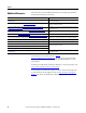
Rockwell Automation Support Rockwell Automation provides technical information on the Web to assist you in using its products. At http://www.rockwellautomation.com/support/, you can find technical manuals, a knowledge base of FAQs, technical and application notes, sample code and links to software service packs, and a MySupport feature that you can customize to make the best use of these tools.