
User Manual


Rockwell Automation Publication 750COM-UM008A-EN-P - July 2012 9
Chapter 1
Getting Started
The 20-750-ENETR Option Module is intended for installation into a
PowerFlex 750-Series drive and is used for network communication.
Components
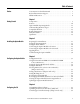
Topic Page
Components
9
Features
10
Option Module Operating Modes
11
Compatible Products
13
Required Equipment
13
Safety Precautions 14
Quick Start 15
➊
➋
➌
➍
➎
➏
0
5
4
9
3
8
2
7
1
6
0
5
4
9
3
8
2
7
1
6
0
5
4
9
3
8
2
7
1
6
MODE
ADPTR
TAP
J4
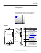
Item Part Description
➊
Status Indicators Four status indicators that indicate the
status of the option module and network
communication. See Chapter 7,
Troubleshooting.
➋
Node Address
Switches
Sets the network node address of the
option module when not using:
• A BOOTP or DHCP server
• Option module parameters
See Setting the Node Address
on page 20.
➌
Operating Mode
Jumper (J4)
Selects the mode in which the option
module operates. See Setting the
Operating Mode on page 19.
➍
ENET1 Network
Port
RJ-45 connector for the Ethernet network
cable. The connector is CAT-5 compliant
to ensure reliable data transfer on
100Base-TX Ethernet connections. Either
port may be used in Adapter mode.
➎
ENET2 Network
Port
➏
ENET3 (DEVICE)
Port (PowerFlex
755 only)
RJ-45 connector to connect the short
Ethernet cable (provided with the option
module) to the Ethernet port on the
PowerFlex 755 drive embedded EtherNet/
IP adapter. This is intended for ‘Integrated
Motion on the EtherNet/IP network’ data
transfer.
Component Side View Top View