
User Manual

150 Rockwell Automation Publication 750COM-UM008A-EN-P - July 2012
Appendix B Option Module Parameters
Parameters for Tap Mode
Operation
This section contains a list of Device parameters available when the option
module is operated in Tap mode.
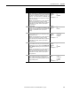
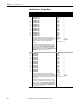
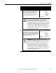
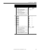
Device Parameters—Tap Mode
Parameter
No. Name and Description Details
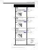
01 [Operating Mode]
Displays the option module’s operating mode set with the
Operating Mode Jumper J4 (Figure 1 on page 19
).
Values: 0 = Adapter
1 = Tap
Type: Read Only
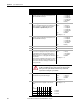
02 [Port Number]
Displays the drive port into which the option module is installed.
Typically, this is Port 4, 5 or 6.
Minimum: 4
Maximum: 6
Type: Read Only
03 [Reserved]
04 [Reserved]
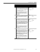
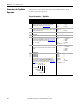
05 [Net Addr Sel]
Selects the source from which the option module’s node address
is taken when the Node Address switches (Figure 2 on page 21
)
are not being used (that is, switches set to any value other than
001…254 or 888).
Default: 3 = DHCP
Values: 1 = Parameters
2 = BOOTP
3 = DHCP
Type: R ea d/Wr ite
Reset Required: Yes
06 [Net Addr Src]
Displays the source from which the option module’s node address
is taken.
Values: 0 = Switches
1 = Parameters
2 = BOOTP
3 = DHCP
Type: Read Only
07
08
09
10
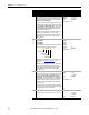
[IP Addr Cfg 1]
[IP Addr Cfg 2]
[IP Addr Cfg 3]
[IP Addr Cfg 4]
Sets the IP address bytes for the option module’s network
address when Device Parameter 05 - [Net Addr Sel] is set to
“1” (Parameters) and the Node Address switches (Figure 2 on
page 21) are not being used (that is, switches set to any value
other than 001…254 or 888).
Default: 0
Default: 0
Default: 0
Default: 0
Minimum: 0
Maximum: 255
Type: R ea d/Wr ite
Reset Required: Yes
255 . 255 . 255 . 255
[IP Addr Cfg 1]
[IP Addr Cfg 2]
[IP Addr Cfg 3]
[IP Addr Cfg 4]