
User Manual


122 Rockwell Automation Publication 750COM-UM008A-EN-P - July 2012
Chapter 7 Troubleshooting
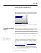
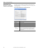
Viewing and Clearing Events
The option module has an event queue to record significant events that occur in
the operation of the module. When such an event occurs, an entry consisting of
the event’s numeric code and a timestamp is put into the event queue. You can
view the event queue with the PowerFlex 20-HIM-A6 or 20-HIM-C6S HIM,
DriveExplorer software, version 6.01 or later, DriveExecutive software, version
5.01 or later, or other clients using the DPI Fault object. For details on viewing
and clearing events with the HIM, see the PowerFlex 20-HIM-A6/-C6S HIM
(Human Interface Module) User Manual, publication 20HIM-UM001
.
The event queue can contain up to 32 entries, which are stored in an EEPROM
chip—making the event queue nonvolatile. Eventually the event queue will
become full, since its contents are retained through option module power cycles
and resets. At that point, a new entry replaces the oldest entry. Only an event
queue clear operation or the corruption of the EEPROM group containing the
event queue will clear the event queue contents. In the latter case, the option
module will not generate a fault to indicate that the event queue was corrupted.
Resetting the option module to defaults has no effect on the event queue, other
than to log a Code 58 “Module Defaulted” event.
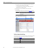
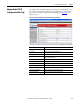
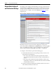
Many events in the event queue occur under normal operation. If you encounter
unexpected communication problems, the events may help you or Allen-Bradley
personnel troubleshoot the problem. The following events may appear in the
event queue.
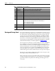
67 Net Rx Overruns The number of receive buffer overruns reported by the Ethernet hardware.
68 Net Rx Packets The number of Ethernet packets that the option module has received.
69 Net Rx Errors The number of receive errors reported by the Ethernet hardware.
70 Net Tx Packets The number of Ethernet packets that the option module has sent.
71 Net Tx Errors The number of transmit errors reported by the Ethernet hardware.
72 Reserved —
73 Net Addr Sw The present value of the option module node address (rotary) switches.
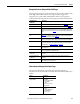
74 MDIX Status Indicates the type of cable connected to the option module’s ports.
P1 = ENET1 network port, P2 = ENET2 network port, and P3 = ENET3 (DEVICE) port.
Bit 0 - P1 Normal; Bit 1 - P1 Swapped;
Bit 2 - P2 Normal; Bit 3 - P2 Swapped;
Bit 4 - P3 Normal; Bit 5 - P3 Swapped
75 Boot Flash Count Number of times the boot firmware in the option module has been upgraded.
76 App Flash Count Number of times the application firmware in the option module has been upgraded.
77 FPGA Flash Count Number of times the FPGA configuration in the option module has been upgraded.
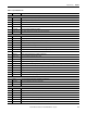
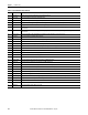
Table 11 - Tap Mode Diagnostic Items (Continued)
No. Name Description