User Manual PowerFlex 20-750-ENETR Dual-port EtherNet/IP Option Module Firmware Revision Number 1.
Important User Information Solid-state equipment has operational characteristics differing from those of electromechanical equipment. Safety Guidelines for the Application, Installation and Maintenance of Solid State Controls (publication SGI-1.1 available from your local Rockwell Automation® sales office or online at http://www.rockwellautomation.com/literature/) describes some important differences between solid-state equipment and hard-wired electromechanical devices.
Table of Contents Preface Conventions Used in This Manual . . . . . . . . . . . . . . . . . . . . . . . . . . . . . . . . . 7 Rockwell Automation Support . . . . . . . . . . . . . . . . . . . . . . . . . . . . . . . . . . . . . 7 Additional Resources . . . . . . . . . . . . . . . . . . . . . . . . . . . . . . . . . . . . . . . . . . . . . . 8 Chapter 1 Getting Started Components. . . . . . . . . . . . . . . . . . . . . . . . . . . . . . . . . . . . . . . . . . . . . . . . . . . . . . 9 Features . . . . .
Table of Contents Chapter 5 Using the I/O (Adapter mode only) About I/O Messaging . . . . . . . . . . . . . . . . . . . . . . . . . . . . . . . . . . . . . . . . . . . . Understanding the I/O Image . . . . . . . . . . . . . . . . . . . . . . . . . . . . . . . . . . . . . Using Logic Command/Status . . . . . . . . . . . . . . . . . . . . . . . . . . . . . . . . . . . . Using Reference/Feedback . . . . . . . . . . . . . . . . . . . . . . . . . . . . . . . . . . . . . . . . Using Datalinks . . . . . . . . .
Table of Contents Appendix C EtherNet/IP Objects (Adapter mode only) Supported Data Types . . . . . . . . . . . . . . . . . . . . . . . . . . . . . . . . . . . . . . . . . . . Identity Object. . . . . . . . . . . . . . . . . . . . . . . . . . . . . . . . . . . . . . . . . . . . . . . . . . Assembly Object . . . . . . . . . . . . . . . . . . . . . . . . . . . . . . . . . . . . . . . . . . . . . . . . Register Object. . . . . . . . . . . . . . . . . . . . . . . . . . . . . . . . . . . . . . . . . . . . . .
Table of Contents Notes: 6 Rockwell Automation Publication 750COM-UM008A-EN-P - July 2012
Preface This manual provides information about the 20-750-ENETR Dual-port EtherNet/IP Option Module for network communication and how to use the module with PowerFlex 750-Series drives. Conventions Used in This Manual The following conventions are used throughout this manual: • Parameter names are shown in the format Device Parameter xx - [*] or Host Parameter xx - [*]. The xx represents the parameter number. The * represents the parameter name—for example, Device Parameter 01 [Operating Mode].
Preface Additional Resources These documents contain additional information concerning related products from Rockwell Automation. Resource Description Network Communication Option Module Installation Instructions, publication 750COM-IN002 Information on the installation of PowerFlex® 750-Series Network Communication Modules. EtherNet/IP Media Planning and Installation Manual, ODVA publication 148 (1) Information on the planning, installation, and techniques used to implement an EtherNet/IP network.
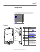
Chapter 1 Getting Started The 20-750-ENETR Option Module is intended for installation into a PowerFlex 750-Series drive and is used for network communication. Topic Page Components 9 Features 10 Option Module Operating Modes 11 Compatible Products 13 Required Equipment 13 Safety Precautions 14 Quick Start 15 Components ➊ Item Part ➊ Status Indicators Four status indicators that indicate the status of the option module and network communication. See Chapter 7, Troubleshooting.
Chapter 1 Getting Started Features The features of the option module include the following: • Adapter or Tap mode of operation that is selected by using the Operating Mode Jumper ( J4). In Adapter mode (default), the option module operates as a network communication adapter supporting star, linear or device-level ring (DLR) network topologies.
Getting Started Chapter 1 • Master-Slave or Peer-to-Peer hierarchy that can be configured to transmit data to and from a controller or another PowerFlex 750-Series drive on the network by using another 20-750-ENETR option module or the embedded EtherNet/IP adapter in a PowerFlex 755 drive. • Supports ‘Integrated Motion on the EtherNet/IP network’ operation (Tap mode only) for only the PowerFlex 755 drive, firmware revision 2.003 or later.
Chapter 1 Getting Started used in a linear or device-level ring (DLR) network topology. When using a star network topology, either the ENET1 or ENET2 network port may be used. In Adapter mode, the ‘Integrated Motion on the EtherNet/IP network’ functionality is not supported. Tap Mode (only with PowerFlex 755 drives) In the Tap mode, the option module operates like a gateway and functions similar to the 1783-ETAP module.
Getting Started Compatible Products Chapter 1 At the time of publication, the option module is compatible with the following: • PowerFlex 753 drives (all firmware revisions) • PowerFlex 755 drives (firmware revision 1.010 or later) (1) (1) When the option module is connected to an incompatible drive, its PORT status indicator will flash orange indicating that it is not compatible with the drive.
Chapter 1 Getting Started Safety Precautions Please read the following safety precautions carefully. ATTENTION: Risk of injury or death exists. The PowerFlex drive may contain high voltages that can cause injury or death. Remove all power from the PowerFlex drive, and then verify power has been discharged before installing or removing the option module. ATTENTION: Risk of injury or equipment damage exists.
Getting Started Quick Start Chapter 1 This section is provided to help experienced users quickly start using the option module in Adapter mode or Tap mode. If you are unsure how to complete a step, refer to the referenced chapter. Adapter Mode of Operation Step Action See 1 Review the safety precautions for the option module. Throughout this manual 2 Verify that the PowerFlex drive is properly installed.
Chapter 1 Getting Started Tap Mode of Operation (only with PowerFlex 755 drives) Step Action See 1 Review the safety precautions for the option module. Throughout this manual 2 Verify that the PowerFlex drive is properly installed. PowerFlex 750-Series AC Drive Installation Instructions, publication 750-IN001 3 Set the option module IP address. a. When using the option module node address switches, set the IP address now and proceed with step 4.
Chapter 2 Installing the Option Module This chapter provides instructions for installing the option module in a PowerFlex 750-Series drive.
Chapter 2 Installing the Option Module Much of EtherNet/IP implicit (I/O) messaging uses IP multicast to distribute I/O control data, which is consistent with the CIP producer/ consumer model. Historically, most switches have treated multicast packets the same as broadcast packets. That is, all multicast packets are retransmitted to all ports.
Installing the Option Module The option module can be operated in Adapter mode (default) or Tap mode. For information about the operating modes, see Option Module Operating Modes on page 11. Before installing the option module, set its Operating Mode Jumper J4 (Figure 1) for the desired mode of operation. If Operating Mode Jumper J4 is missing, the option module operates in the Adapter mode.
Chapter 2 Installing the Option Module Setting the Node Address There are four methods for configuring the option module node address: • Node Address Switches — Use these switches when working on a simple, isolated network (for example, 192.168.1.xxx) that has other products with switches to set their IP addresses, does not need to be accessed from outside the network, and you prefer a simplified node addressing method.
Installing the Option Module Chapter 2 If the PowerFlex 750-Series drive is connected to a Stratix 6000 or Stratix 8000 managed Ethernet switch and the drive is set for BOOTP mode, the “dynamic IP address assignment by port” (Stratix 6000) or “DHCP persistence” (Stratix 8000) feature will set the IP address for the drive.
Chapter 2 Installing the Option Module Settings Description 888 Resets the option module network node address to factory defaults. Thereafter, the drive must be powered down, the Node Address switches must be set to a correct value (001…254), and then the drive must be powered up again to accept the new address.
Installing the Option Module Connecting the Option Module to the Network Chapter 2 The option module is connected to the network differently depending on the mode in which the option module is operated. When Operating in Adapter Mode ATTENTION: Risk of injury or death exists. The PowerFlex drive may contain high voltages that can cause injury or death. Remove power from the drive, and then verify power has been discharged before connecting the option module to the network. 1.
Chapter 2 Installing the Option Module Figure 4 - Connecting the Ethernet Cable in a Linear Topology Network To other EtherNet/IP networks PowerFlex 750-Series Drives (1) (with 20-750-ENETR Option Modules) Controller (ControlLogix controller shown with 1756-ENBT Bridge) Computer with Ethernet Connection Ethernet Switch (1) The option module’s ENET1 and ENET2 network ports are used.
Installing the Option Module Chapter 2 When Operating in Tap Mode (only PowerFlex 755 drives) ATTENTION: Risk of injury or death exists. The PowerFlex drive may contain high voltages that can cause injury or death. Remove power from the drive, and then verify power has been discharged before connecting the option module to the network. 1. Remove power from the drive. 2. Remove the drive cover and lift up the drive HIM bezel to its open position to access the drive control pod. 3.
Chapter 2 Installing the Option Module Applying Power ATTENTION: Risk of equipment damage, injury, or death exists. Unpredictable operation may occur if you fail to verify that parameter settings are compatible with your application. Verify that settings are compatible with your application before applying power to the drive. Apply power to the drive. The option module receives its power from the drive.
Installing the Option Module Chapter 2 Table 1 - Adapter Mode – Drive and Option Module Start-Up Status Indications Item Name Color State Description Drive STS Indicator ➊ STS (Status) Green Flashing Drive ready but not running, and no faults are present. Steady Drive running, no faults are present. Flashing When running, a type 2 (non-configurable) alarm condition exists – drive continues to run.
Chapter 2 Installing the Option Module Table 2 - Tap Mode – PowerFlex 755 Drive and Option Module Start-Up Status Indications Item Name Color State Description Drive STS Indicator ➊ STS (Status) Green Flashing Drive ready but not running, and no faults are present. Steady Drive running, no faults are present. Flashing When running, a type 2 (non-configurable) alarm condition exists – drive continues to run.
Installing the Option Module Chapter 2 Configuring and Verifying Key Drive Parameters The PowerFlex 750-Series drive can be separately configured for the control and Reference functions in various combinations. For example, you could set the drive to have its control come from a peripheral or terminal block with the Reference coming from the network. Or you could set the drive to have its control come from the network with the Reference coming from another peripheral or terminal block.
Chapter 2 Installing the Option Module problem occurs, this verification step provides the diagnostic capability to determine whether the drive/option module or the network is the cause. 4. If hard-wired discrete digital inputs are not used to control the drive, verify that all unused digital input drive parameters are set to “0” (Not Used). Commissioning the Option Module To commission the option module, you must set a unique network node address. See the Glossary for details about IP addresses.
Chapter 3 Configuring the Option Module This chapter provides instructions and information for setting the parameters to configure the option module.
Chapter 3 Configuring the Option Module Using the PowerFlex 20-HIMA6 or 20-HIM-C6S HIM to Access Parameters If your drive has an enhanced PowerFlex 20-HIM-A6 or 20-HIM-C6S HIM, it can be used to access parameters in the option module. 1. Display the Status screen, which is shown on HIM powerup. 2. Use the or module is installed. key to scroll to the Port in which the option 3. Press the PAR# soft key to display the Jump to Param # entry pop-up box. 4.
Configuring the Option Module Chapter 3 1. Depending on the type of server (BOOTP or DHCP) being used, set Device Parameter 05 - [Net Addr Sel] to either “2” (BOOTP) or “3” (DHCP) respectively. Stopped 0.00 Hz Edit Net Addr Sel AUTO F DHCP 1 ESC ▲ << 3 ▼ 3 ENTER Value Setting 1 Parameters 2 BOOTP 3 DHCP (default) 2. Note the option module’s hardware Ethernet Address (MAC), which will be used in step 7.
Chapter 3 Configuring the Option Module The BOOTP/DHCP Server dialog box appears. To properly configure devices on the EtherNet/IP network, you must configure settings in the BOOTP/DHCP software to match the network. 4. From the Tools menu, choose Network Settings. The Network Settings dialog box opens. 5. Edit the following: Box Subnet Mask Type (1) The subnet mask for the option module’s network. Gateway (1) The IP address of the gateway device on the option module’s network.
Configuring the Option Module Chapter 3 7. In the BOOTP/DHCP Request History list, either double-click the option module’s Ethernet Address (MAC) noted in step 2, or click New in the Relation List. The New Entry dialog box appears. In the first instance, the Ethernet Address (MAC) is automatically entered. In the latter instance, it must be manually entered. 8.
Chapter 3 Configuring the Option Module Using Option Module Parameters By default, the option module is configured to use a DHCP server as the source for the IP address, subnet mask, and gateway address for the option module. To use option module parameters instead, you must first change the source for the node address to “Parameters” and then set the associated option module parameters as described in the following subsections. Changing the Source for the Node Address 1.
Configuring the Option Module Chapter 3 Setting the Subnet Mask 1. Verify that Device Parameter 05 - [Net Addr Sel] is set to “1” (Parameters). 2. Set the value of Device Parameters 11 - [Subnet Cfg 1] through 14 [Subnet Cfg 4] to the desired value for the subnet mask. Default = 0.0.0.0 255 . 255 . 255 . 255 Stopped 0.00 Hz AUTO F Edit Subnet Cfg 1 0 0 << 255 ESC ENTER [Subnet Cfg 1] [Subnet Cfg 2] [Subnet Cfg 3] [Subnet Cfg 4] 3.
Chapter 3 Configuring the Option Module Setting the Data Rate By default, the option module is set to autodetect, so it automatically detects the data rate and duplex setting used on the network. If you need to set a specific data rate and duplex setting, the value of Device Parameter 19 - [Net Rate Cfg 1] determines the Ethernet data rate and duplex setting that will be used to communicate on the option module’s ENET1 network port. For definitions of data rate and duplex, see the Glossary. 1.
Configuring the Option Module Selecting Master-Slave or Peer-to-Peer Hierarchy (Adapter mode only) Chapter 3 This procedure is only required if Datalinks are used to write or read data of the drive or its connected peripherals. A hierarchy determines the type of device with which the option module exchanges data. In a Master-Slave hierarchy, the option module exchanges data with a master, such as a scanner or bridge.
Chapter 3 Configuring the Option Module Using the formula, the value for Host Parameter 01 - [DL From Net 01] would be (10000 * 5) + (3) = 50003. Follow these steps to enable Datalinks to write data. 1. Set the values of only the required number of contiguous controller-todrive Datalinks needed to write data to the drive and that are to be included in the network I/O connection. 2. Reset the option module; see Resetting the Option Module on page 49. 3.
Configuring the Option Module Chapter 3 When using a ControlLogix controller and the Generic Profile, configure the Datalink parameters now as described in this section. Host Parameters 17 - [DL To Net 01] through 32 - [DL To Net 16] configure which parameters in the drive, option module, or any other connected peripheral send the values to the network.
Chapter 3 Configuring the Option Module 1. Set Device Parameters 41 - [To Peer Period] and 42 - [To Peer Skip] as desired for your application. Parameter 41 controls how frequently the option module will transmit data when it is changing. Parameter 42 controls how frequently the option module will transmit data when it is not changing. 2. Set Host Parameter 31 - [DL To Net 15] to point to the drive parameter [Drive Logic Rslt], which is parameter 879 for PowerFlex 753 drives and PowerFlex 755 drives. 3.
Configuring the Option Module Chapter 3 1. Decide how many Datalink parameters you want to transmit, and set Device Parameter 39 - [DLs To Peer Cfg] to that value. 2. Determine how the Datalinks are allocated. The highest numbered of the 16 Datalinks are allocated to peer I/O. For example, if Device Parameter 39 - [DLs To Peer Cfg] is set to “3,” then Datalinks 14, 15, and 16 are allocated to peer I/O.
Chapter 3 Configuring the Option Module 4. Set Device Parameter 32 - [Fr Peer Timeout] to a suitable timeout value for your application. This value should be greater than the product of Device Parameter 41 [To Peer Period] and Device Parameter 42 - [To Peer Skip] in the transmitting drive. Stopped 0.00 Hz AUTO F Edit Fr Peer Timeout 10.00 Secs 0.01 << 10.00 . ESC ENTER 5.
Configuring the Option Module Chapter 3 7. If a Logic Command is being sent, use Device Parameter 30 - [Logic Src Cfg] to set the number of the Datalink that contains the Logic Command within the range defined by Device Parameter 28 - [DLs Fr Peer Cfg]. For example, if Device Parameter 28 - [DLs Fr Peer Cfg] is set to receive five Datalinks (Datalinks 12 through 16) and the first of those five Datalinks (Datalink 12) contains the Logic Command, set Device Parameter 30 - [Logic Src Cfg] to a value of “1.
Chapter 3 Configuring the Option Module By default, when communication is disrupted (for example, the network cable is disconnected), the controller is idle (in program mode or faulted), and/or peer I/O or explicit messaging for drive control is disrupted, the drive responds by faulting if it is using I/O from the network. You can configure a different response to these events: • Disrupted I/O communication by using Host Parameter 33 - [Comm Flt Action].
Configuring the Option Module Chapter 3 Changes to these parameters take effect immediately. A reset is not required. If communication is disrupted and then is re-established, the drive will automatically receive commands over the network again.
Chapter 3 Configuring the Option Module Setting Web Page Access By using a web browser to access the IP address set for the option module, you can view the option module web pages for information about the module, the drive and other DPI devices connected to the drive, such as HIMs or converters. Depending on its selected operating mode (Adapter or Tap), the option module provides a unique set of web pages with different information. IMPORTANT By default, the option module web pages are disabled.
Configuring the Option Module Resetting the Option Module Chapter 3 Changes to switch and jumper settings and some option module parameters require you to reset the option module before the new settings take effect. You can reset the option module by power cycling the drive or by using Device Parameter 25 - [Reset Module]. ATTENTION: Risk of injury or equipment damage exists. If the option module is transmitting control I/O to the drive, the drive may fault when you reset the option module.
Chapter 3 Configuring the Option Module Restoring Option Module Parameters to Factory Defaults As an alternate reset method, you can restore the option module parameters by using a MEMORY folder menu item instead of using Device Parameter 25 [Reset Module] described in Resetting the Option Module on page 49. The MEMORY folder method provides two ways to restore the option module Device and Host parameters: • ALL—restores ALL option module Device and Host parameters to their factory default values.
Configuring the Option Module Chapter 3 press the ESC soft key to cancel. IMPORTANT When performing a Set Defaults, the drive may detect a conflict and then not allow this function to occur. If this happens, first resolve the conflict and then repeat this Set Defaults procedure. Common reasons for a conflict include the drive running or a controller in Run mode. 9.
Chapter 3 Configuring the Option Module Updating the Option Module Firmware The option module firmware can be updated over the network or serially through a direct connection from a computer to the drive using a 1203-USB or 1203-SSS serial converter. When updating firmware over the network, you can use the Allen-Bradley ControlFLASH software tool, the built-in update capability of DriveExplorer Lite or Full software, or the built-in update capability of DriveExecutive software.
Chapter 4 Configuring the I/O This chapter provides instructions on how to configure a Rockwell Automation ControlLogix controller to communicate with the option module and connected PowerFlex drive. For information on using a PLC-5, SLC 500, or MicroLogix 1100/1400 controller, see Controller Examples for EtherNet/IP Network Communications with PowerFlex 750-Series Drives, publication 750COM-AT001.
Chapter 4 Configuring the I/O The Configure Drivers dialog box reappears with the new driver in the Configured Drivers list. 9. Click Close to close the Configure Drivers dialog box. 10. Keep RSLinx software running and verify that your computer recognizes the drive. a. From the Communications menu, choose RSWho. b. In the menu tree, click “+” next to the Ethernet driver. Note that two other RSLinx drivers (Ethernet devices or Remote Devices via Linx Gateway) may be used.
Configuring the I/O Chapter 4 Figure 10 - Example ControlLogix Controller EtherNet/IP Device-level Ring Network To other EtherNet/IP networks IP Address 10.91.96.101 (1st Drive) PowerFlex 750-Series Drives (each a with 20-750-ENETR Option Module) IP Address 10.91.96.
Chapter 4 Configuring the I/O The Select Module dialog box appears. 4. Expand the Communications group to display all of the available communication modules. 5. In the list, select the EtherNet/IP bridge used by your controller. In this example, we use a 1756-EN2TR EtherNet/IP Bridge (Series A), so the 1756-EN2TR/A option is selected. 6. Click OK. 7. In the Select Major Revision pop-up dialog box, select the major revision of its firmware. 8. Click OK. The bridge’s New Module dialog box appears. 9.
Configuring the I/O Box Revision Electronic Keying Chapter 4 Setting Click Change to change Revision or Electronic Keying. The minor revision of the firmware in the bridge. (You already set the major revision by selecting the bridge series in step 5.) Compatible Module. The “Compatible Module” setting for Electronic Keying verifies that the physical module is consistent with the software configuration before the controller and bridge make a connection.
Chapter 4 Configuring the I/O • Unicast connection (RSLogix 5000 software, version 18.00 or later) • Drive Add-on Profiles, version 2.01 or later, enable I/O to be added online while the controller is in Run mode. • Drive Add-on Profiles can be updated anytime. When a new drive is used or to benefit from new updates for Add-on Profiles, you will need the newest Add-on Profile update. Go to www.ab.com/support/abdrives/ webupdate to download the latest RSLogix 5000 drive Add-on Profile.
Configuring the I/O Chapter 4 The drive’s New Module dialog box appears. 4. On the General tab, edit the following data about the drive/option module. Box Setting Name A name to identify the drive. Description Optional – description of the drive/option module. IP Address The IP address of the option module. 5. On the New Module dialog box in the Module Definition section, click Change to launch the Module Definition dialog box and begin the drive/ option module configuration process.
Chapter 4 Configuring the I/O 6. In the Module Definition dialog box, edit the following information. Box Setting Revision The major and minor revision of the firmware (database) in the drive. If the drive’s major and minor revision is not available, the drive database is not installed on your computer. To get the correct database revision, use one of the following buttons at the bottom left of the Module Definition dialog box: • Create Database: Creates a database from an online network drive.
Configuring the I/O Chapter 4 parameters. The procedure to configure the Datalinks on the Module Definition dialog box for the Input Data and Output Data is the same. a. Click the button in the topmost blank row to display the Parameter Properties dialog box for the corresponding Datalink. IMPORTANT Always use the Datalink parameters in consecutive numerical order, starting with the first parameter.
Chapter 4 Configuring the I/O 8. Click the Connection tab. 9. In the “Requested Packet Interval (RPI)” box, set the value to 2.0 milliseconds or greater (default is 20.0 milliseconds). This value determines the maximum interval that a controller should use to move data to and from the option module. To conserve bandwidth, use higher values for communicating with low priority devices. The “Inhibit Module” box, when checked, inhibits the module from communicating with the RSLogix 5000 project.
Configuring the I/O Chapter 4 Box Setting Enable BootP When this box is checked, BOOTP is enabled in the option module and will ignore the IP address set in the General tab. When unchecked, the controller uses the set IP address. This is another method to enable/disable BOOTP in the option module. For this example, leave this box unchecked. 12. Click Set to save the Port Configuration information which sets the corresponding offline Subnet Cfg x and Gateway Cfg x parameters in the option module. 13.
Chapter 4 Configuring the I/O Figure 12 - Controller Output Tags Saving the I/O Configuration to the Controller After adding the bridge and drive/option module to the I/O configuration, you must download the configuration to the controller. You should also save the configuration to a file on your computer. 1. From the Communications menu in the RSLogix 5000 dialog box, choose Download. The Download dialog box appears.
Configuring the I/O TIP Chapter 4 If a message box reports that RSLogix 5000 software is unable to go online, find your controller in the Who Active dialog box. From the Communications menu, choose Who Active. After finding and selecting the controller, click Set Project Path to establish the path. If your controller does not appear, you need to add or configure the EtherNet/IP driver with RSLinx software. See Using RSLinx Classic Software on page 53 and RSLinx online help for details. 2.
Chapter 4 Configuring the I/O 2. Click the Drive tab. 3. Click Connect to Drive to begin the correlation process. After the drive configuration data has been verified, a pop-up dialog box appears, which synchronizes ports from the online drive to the project to be sure that the correct Datalinks are assigned. 4. Click OK. If the Differences Found dialog box appears—which is typical, click Download. This will download the project settings from the controller to the drive and its connected option module.
Configuring the I/O Chapter 4 6. To match the Datalinks in the drive to the project I/O configuration, click Use Project. After the Datalinks have been matched, the Input Data and Output Data columns are grayed out. 7. Click Continue. A series of download dialog boxes appear, which may take a minute to complete.
Chapter 4 Configuring the I/O process and saves the user time. It is particularly beneficial in a drive replacement situation when a production line is down. TIP Use with Stratix 6000 and 8000 switches to provide dynamic IP address assignment by port. This eliminates the need for the user to manually enter the IP address, Subnet mask, and Gateway address prior to connecting a replacement drive to the Ethernet network. ADC can also work in tandem with Firmware Supervisor.
Configuring the I/O Chapter 4 Version 4.02 (or later) Drive Add-on Profiles (AOPs) Version 4.02 Drive AOPs require user action to enable ADC. This helps verify that the user understands ADC operation prior to turning it on. Note the following ADC operating status when using version 4.02 (or later) Drive AOPs: • When adding a new drive, ADC is disabled by default for any drive that supports ADC, such as PowerFlex 753 drives with firmware 7.001 or later, or PowerFlex 755 drives with firmware 4.001 or later.
Chapter 4 Configuring the I/O 1. Open the drive General tab dialog box. 2. Click Change to open the Module Definition dialog box. 3. Select the appropriate Electronic Keying for your application. There are three Electronic Keying choices available in the Module Definition dialog box in the Drive AOP, but only two are recommended with ADC.
Configuring the I/O Chapter 4 Electronic Keying Selection Recommendation Compatible Module This selection is the typical ADC selection when Firmware Supervisor is not used. A replacement drive (including peripherals) will need to have the same or higher firmware revision as the original. Since drives with newer firmware are required to be compatible with older firmware, this allows ADC to work without compatibility concerns.
Chapter 4 Configuring the I/O 6. Click the Port Properties icon to open the Properties dialog box. There are two checkboxes related to ADC. Checkbox Selection Description Enable Automatic Device Configuration See the Important note on page 68 and, depending on the Drive AOP version being used, Version 4.01 Drive Add-on Profiles (AOPs) on page 68 or Version 4.02 (or later) Drive Add-on Profiles (AOPs) on page 69 for additional information about ADC use and Logix behavior.
Configuring the I/O 11. Click the ADC icon Chapter 4 to open the ADC Settings dialog box. The ADC Settings dialog box provides a single location for ADC configuration of the drive’s ports. Global checkboxes at the top of each column checks or unchecks the entire column. Ports can also be turned on/off individually. See the checkbox selection information in step 3 for additional details.
Chapter 4 Configuring the I/O 14. Save your RSLogix 5000 project and download the project to the Logix controller. IMPORTANT Note that some parameters can affect the minimum/maximum of other parameters and can cause the settings of these parameters to be “out of range.” This, in turn, will cause ADC to fail with a module fault (code 16#0010) “Mode or state of module does not allow object to perform requested service.
Configuring the I/O Chapter 4 Storing the Drive’s and Peripherals’ Firmware in the Logix Controller (Firmware Supervisor) The Logix Firmware Supervisor function has been extended to provide firmware updates for the peripherals connected to the drive. You must be online and in program mode with the controller to load/store the firmware supervisor settings. To configure the controller to check and refresh the correct firmware for the drive and peripherals, perform the following steps. 1.
Chapter 4 Configuring the I/O The Nonvolatile Memory Load/Store dialog box appears. 9. From the Automatic Firmware Update pull-down menu, choose Enable and Store Files to Image. 10. Click <-- Store. You may see two different continue confirmation dialog boxes relating to communication disruptions and erasure of the current contents of the storage card. If okay, click Yes on either dialog box. 11. RSLogix 5000 software will go to the Offline state, and the following dialog box will appear.
Configuring the I/O Chapter 4 5. Click Enabled to enable DeviceLogix after ADC. If you do not set up the automatic method described above to enable DeviceLogix after ADC, you can still do so manually. To enable the DeviceLogix program, set DeviceLogix Parameter 53 - [DLX Operation] to “0” (Enable Logic) by using one of these methods: • An explicit message in the Logix program to write to the parameter. • A HIM or drive software tool to set the parameter.
Chapter 4 Configuring the I/O Module to allow either locking via parameter 5 or password changing via parameters 13 and 17. IMPORTANT Do not set Safe Speed Monitor Module parameter 5 [Lock State] to “1” (Lock); or parameter 6 [Operating Mode] to “1” (Run) in the Add-on Profile configuration before saving the configuration to the controller. Setting these parameters would lock the Module and prevent writing the higher numbered parameters, thus causing the ADC download to fail.
Configuring the I/O Chapter 4 A configuration signature is generated. 2. Access Safe Speed Monitor Module parameter 10 [Signature ID] and record the configuration signature value stored in this parameter. 3. Enter the current password for the Safe Speed Monitor Module into parameter 1 [Password]. 4. Set Safe Speed Monitor Module parameter 5 [Lock State] to “1” (Lock).
Chapter 4 Configuring the I/O Additional information may also be displayed on the HIM if it is present (upgrade status, and so forth). If ADC is unsuccessful, the NET A status indicator will be flashing green or off, and RSLogix 5000 software can be used to get additional information. When online, the drive at issue should have a yellow triangle next to it in the RSLogix 5000 project's I/O Configuration folder. Double-click the drive to open the Drive AOP.
Configuring the I/O Chapter 4 • A project must maintain specific revision level control. • The controller cannot be taken offline. RSLogix 5000 software, version 16.00 or later, enables the drive Generic Profile to be added while the controller is online and in the Run mode. Adding the Drive/Option Module to the I/O Configuration To transmit data between the bridge and the drive, you must add the drive as a child device to the parent bridge. 1.
Chapter 4 Configuring the I/O 5. Edit the following information about the drive and option module. Box Setting Name A name to identify the drive and option module. Description Optional – description of the drive/option module. Comm Format Data - DINT (This setting formats the data in 32-bit words.) IP Address The IP address of the option module.
Configuring the I/O Chapter 4 For the example in this manual, all 16 Host [DL From Net xx] and all 16 Host [DL To Net xx] are used, resulting in an Input Size of “19” and an Output Size of “18.” 7. After setting the information in the drive’s New Module dialog box, click OK. The Module Properties dialog box appears. 8. Click the Connection tab. 9. In the “Requested Packet Interval (RPI)” box, set the value to 2.0 milliseconds or greater (default is 20.0 milliseconds).
Chapter 4 Configuring the I/O Figure 13 - Input Image Controller Tags Figure 14 - Output Image Controller Tags Saving the I/O Configuration to the Controller After adding the bridge and drive/option module to the I/O configuration, you must download the configuration to the controller. You should also save the configuration to a file on your computer. TIP When using RSLogix 5000 software, version 16.
Configuring the I/O Chapter 4 The Download dialog box appears. TIP If a message box reports that RSLogix 5000 software is unable to go online, find your controller in the Who Active dialog box. From the Communications menu, choose Who Active. After finding and selecting the controller, click Set Project Path to establish the path. If your controller does not appear, you need to add or configure the EtherNet/IP driver with RSLinx software.
Chapter 4 Configuring the I/O Notes: 86 Rockwell Automation Publication 750COM-UM008A-EN-P - July 2012
Chapter 5 Using the I/O (Adapter mode only) This chapter provides information and examples that explain how to control, configure, and monitor a PowerFlex 750-Series drive using the configured I/O. Topic Page About I/O Messaging 87 Understanding the I/O Image 88 Using Logic Command/Status 89 Using Reference/Feedback 89 Using Datalinks 90 Example Ladder Logic Program Information 91 ControlLogix Controller Example 92 ATTENTION: Risk of injury or equipment damage exists.
Chapter 5 Using the I/O (Adapter mode only) Understanding the I/O Image The terms input and output are defined from the controller’s point of view. Therefore, output I/O is data that is produced by the controller and consumed by the option module. Input I/O is status data that is produced by the option module and consumed as input by the controller. The I/O image will vary based on the following: • How many of the drive’s 32-bit Datalinks (Host DL From Net 01-16 and Host DL To Net 01-16) are used.
Using the I/O (Adapter mode only) Using Logic Command/Status Chapter 5 The Logic Command is a 32-bit word of control data produced by the controller and consumed by the option module. The Logic Status is a 32-bit word of status data produced by the option module and consumed by the controller. When using a ControlLogix controller, the Logic Command word is always DINT 0 in the output image and the Logic Status word is always: • DINT 0 in the input image when using the drive Add-on Profile.
Chapter 5 Using the I/O (Adapter mode only) When Parameter 300 - [Speed Units] is set to RPM, the other parameters are also in RPM. Table 4 - PowerFlex 750-Series Drive Example Speed Reference/Feedback Scaling Network Reference Value Speed Command Value (2) Output Speed Network Feedback Value 130 Hz 60 Hz (3) 60.0 65.0 65 Hz 60 Hz (3) 60.0 32.5 32.5 Hz 32.5 Hz 32.5 0.0 0 Hz 0 Hz 0.0 -32.5 (1) 32.5 Hz 32.5 Hz 32.5 130.0 (1) The effects of values less than 0.
Using the I/O (Adapter mode only) Chapter 5 could change the makeup of the I/O connection in a running system. The I/O connection with the controller must first be disabled to allow changes to the respective Datalinks.
Chapter 5 Using the I/O (Adapter mode only) ControlLogix Controller Example This section includes information when using an RSLogix 5000 Drive Add-on Profile or a Generic Profile. Creating Ladder Logic Using the RSLogix 5000 Drive Add-on Profiles, Version 16.
Using the I/O (Adapter mode only) Chapter 5 Figure 16 - ControlLogix Controller Example Ladder Logic Program Using a Drive Add-on Profile for Logic Status/Feedback Figure 17 - ControlLogix Controller Example Ladder Logic Program Using a Drive Add-on Profile for Logic Command/Reference Rockwell Automation Publication 750COM-UM008A-EN-P - July 2012 93
Chapter 5 Using the I/O (Adapter mode only) Creating Ladder Logic Using the RSLogix 5000 Generic Profile, All Versions Option Module Parameter Settings for ControlLogix Controller Example These option module settings were used for the example ladder logic program in this section. Option Module Host Parameter Value Description 01 - [DL From Net 01] 370 Points to drive Par. 370 - [Stop Mode A] 02 - [DL From Net 02] 371 Points to drive Par.
Using the I/O (Adapter mode only) Chapter 5 Controller Tags When you add the option module and drive to the I/O configuration (Chapter 4), RSLogix 5000 software automatically creates generic (nondescriptive) controller tags. In this example program, the following controller tags are used. You can expand the Input and Output tags to reveal the input and output configuration. The Input tag for this example requires nineteen 32-bit words of data (Figure 18).
Chapter 5 Using the I/O (Adapter mode only) Program Tags To use the Controller tags that are automatically created, you need to create the following Program tags for this example program.
Using the I/O (Adapter mode only) Chapter 5 Figure 21 - ControlLogix Controller Example Ladder Logic Program Using a Drive Generic Profile for Logic Command/Reference Example Datalink Data The Datalink data used in the example program is shown in Figure 22. Note that to describe the parameters to which the Datalinks are assigned, you may want to add descriptions to the automatically-created generic controller tags or create a UDDT.
Chapter 5 Using the I/O (Adapter mode only) Figure 22 - ControlLogix Controller Example Datalinks for Ladder Logic Program Using a Drive Generic Profile TIP 98 To determine whether a parameter is a 32-bit integer (DINT) or a REAL data type, see the Data Type column in the chapter containing parameters in the PowerFlex 750-Series AC Drives Programming Manual (publication 750PM001).
Chapter 6 Using Explicit Messaging (Adapter mode only) This chapter provides information and examples that explain how to use Explicit Messaging with a ControlLogix controller to configure and monitor the option module and connected PowerFlex 750-Series drive. For explicit messaging with a PLC-5, SLC 500, or MicroLogix 1100/1400 controller, see Controller Examples for EtherNet/IP Network Communications with PowerFlex 750-Series Drives, publication 750COM-AT001.
Chapter 6 Using Explicit Messaging (Adapter mode only) TIP To message to another device in a different drive port, see the Instance table in Appendix C: • DPI Parameter Object section on page 163 for Device parameters. • Host DPI Parameter Object section on page 177 for Host parameters. In the Message Configuration dialog box, set the Instance field to an appropriate value within the range listed for the port in which the device resides.
Using Explicit Messaging (Adapter mode only) Event Description ➍ The controller retrieves the Explicit Message Response from the scanner’s buffer (upload). ➎ The Explicit Message is complete. Chapter 6 For information on the maximum number of Explicit Messages that can be executed at a time, see the documentation for the bridge or scanner and/or controller that is being used.
Chapter 6 Using Explicit Messaging (Adapter mode only) ControlLogix – Formatting a Message to Read a Single Parameter Figure 25 - Get Attribute Single Message Configuration Dialog Boxes The following table identifies the data that is required in each box to configure a message to read a single parameter.
Using Explicit Messaging (Adapter mode only) Chapter 6 ControlLogix Controller Example Ladder Logic Program to Write a Single Parameter A Set Attribute Single message is used to write to a single parameter. This write message example writes a value to the 32-bit REAL (floating point) parameter 535 - [Accel Time 1] in a PowerFlex 750-Series drive.
Chapter 6 Using Explicit Messaging (Adapter mode only) ControlLogix – Formatting a Message to Write a Single Parameter Figure 27 - Set Attribute Single Message Configuration Dialog Boxes The following table identifies the data that is required in each box to configure a message to write a single parameter.
Using Explicit Messaging (Adapter mode only) Chapter 6 ControlLogix Controller Example Ladder Logic Program to Read Multiple Parameters A Scattered Read message is used to read the values of multiple parameters.
Chapter 6 Using Explicit Messaging (Adapter mode only) ControlLogix – Formatting a Message to Read Multiple Parameters Figure 29 - Scattered Read Message Configuration Dialog Boxes The following table identifies the data that is required in each box to configure a message to read multiple parameters. Configuration Tab Example Value Description Message Type Service Type (1) Service Code (1) Class Instance Attribute Source Element Source Length Destination CIP Generic Custom 4d (Hex.) 93 or 9F (Hex.
Using Explicit Messaging (Adapter mode only) Chapter 6 ControlLogix Controller Example Scattered Read Request Data In this message example, we use the data structure in Figure 30 in the source tag named Scattered Read Request to read these five 32-bit REAL (floating point) parameters in a PowerFlex 750-Series drive: • Parameter 001 - [Output Frequency] • Parameter 007 - [Output Current] • Parameter 008 - [Output Voltage] • Parameter 009 - [Output Power] • Parameter 011 - [DC Bus Volts] See DPI Parameter O
Chapter 6 Using Explicit Messaging (Adapter mode only) ControlLogix Controller Example Ladder Logic Program to Write Multiple Parameters A Scattered Write message is used to write to multiple parameters. This write message example writes the following values to these five 32-bit REAL (floating point) parameters in a PowerFlex 750-Series drive: PowerFlex 750-Series Drive Parameter Write Value 536 - [Accel Time 2] 11.1 Sec 538 - [Decel Time 2] 22.2 Sec 575 - [Preset Speed 5] 33.
Using Explicit Messaging (Adapter mode only) Chapter 6 ControlLogix – Formatting a Message to Write Multiple Parameters Figure 33 - Scattered Write Multiple Message Configuration Dialog Boxes The following table identifies the data that is required in each box to configure a message to write multiple parameters. Configuration Tab Example Value Description Message Type Service Type (1) Service Code (1) Class Instance Attribute (2) Source Element Source Length Destination CIP Generic Custom 4e (Hex.
Chapter 6 Using Explicit Messaging (Adapter mode only) ControlLogix Controller Example Scattered Write Request Data In this message example, we use the data structure in Figure 34 in the source tag (Scattered_Write_Request) to write new values to these 32-bit REAL (floating point) parameters: PowerFlex 750-Series Drive Parameter Write Value 536 - [Accel Time 2] 11.1 Sec 538 - [Decel Time 2] 22.2 Sec 575 - [Preset Speed 5] 33.3 Hz 576 - [Preset Speed 6] 44.4 Hz 577 - [Preset Speed 7] 55.
Using Explicit Messaging (Adapter mode only) Chapter 6 ControlLogix Controller – Explanation of Request and Response Data for Read/Write Multiple Messaging The data structures in Figure 36 and Figure 37 use 32-bit words and can accommodate up to 32 parameters in a single message. In the Response Message, a parameter number with Bit 15 set indicates that the associated parameter value field contains an error code (parameter number in response data will be negative).
Chapter 6 Using Explicit Messaging (Adapter mode only) When performing a Scattered Write to REAL data type parameters, the REAL parameter value will need to be COP to the DINT parameter value tag in the Request (Source Data) array.
Chapter 7 Troubleshooting This chapter provides information for diagnosing and troubleshooting potential problems with the option module and network. Understanding the Status Indicators Topic Page Understanding the Status Indicators 113 Indications for Adapter Mode Operation 114 Indications for Tap Mode Operation 116 Viewing Option Module Diagnostic Items 118 Viewing and Clearing Events 122 The option module has four status indicators. They can be viewed with the drive cover removed.
Chapter 7 Troubleshooting Indications for Adapter Mode Operation Use the following sections to troubleshoot the Adapter mode of operation. PORT Status Indicator—Adapter Mode This red/green bicolor LED indicates the status of the option module’s connection to the drive as shown in the table below. Status Cause Corrective Action Off The option module is not powered or is not properly connected to the drive.
Troubleshooting Chapter 7 NET A Status Indicator—Adapter Mode This red/green bicolor LED indicates the status for the network connection as shown in the table below. Status Cause Corrective Actions Off The option module is not powered. The option module is not properly connected to the network. The option module has not acquired its network configuration (IP address, subnet mask, gateway address) from the BOOTP/DHCP server.
Chapter 7 Troubleshooting Indications for Tap Mode Operation Use the following sections to troubleshoot the Tap mode of operation. OK Status Indicator—Tap Mode This red/green bicolor LED indicates the status of the option module as shown in the table below. Status Cause Corrective Action Off The option module is not powered or is not properly connected to the drive.
Troubleshooting Chapter 7 LINK 2 Status Indicator—Tap Mode This green/yellow bicolor LED indicates the status of the ENET2 network port as shown in the table below. Status Cause Corrective Action Off The option module is not properly connected to the network. Securely connect the option module to the network using an Ethernet cable. Also, make sure the Ethernet cable is correctly connected to the Ethernet connector. Steady Green ENET2 network port has a 100 Mbps network link, but no activity.
Chapter 7 Troubleshooting If you encounter unexpected communication problems, the option module’s diagnostic items may help you or Rockwell Automation personnel troubleshoot the problem. Option module diagnostic items can be viewed with the PowerFlex 20-HIM-A6 or 20-HIM-C6S HIM, DriveExplorer software, version 6.01 or later, or DriveExecutive software, version 5.01 or later.
Troubleshooting Chapter 7 Table 10 - Adapter Mode Diagnostic Items (Continued) No. Name Description 27 DL To Net 01 Val 28 DL To Net 02 Val The present value of respective Host DL To Net xx parameter being received from the drive by this option module. (If not using a Datalink, its respective value should be zero.
Chapter 7 Troubleshooting Table 10 - Adapter Mode Diagnostic Items (Continued) No. Name Description 59 60 61 62 Subnet Act 1 Subnet Act 2 Subnet Act 3 Subnet Act 4 Value of each byte in the option module’s present subnet mask. A value of “0” appears if the option module does not currently have a subnet mask. 63 64 65 66 Gateway Act 1 Gateway Act 2 Gateway Act 3 Gateway Act 4 Value of each byte in the option module’s present gateway address.
Troubleshooting Chapter 7 Diagnostic Items for Tap Mode Operation Table 11 - Tap Mode Diagnostic Items No. Name Description 1 Common Logic Cmd The present value of the Common Logic Command being transmitted to the drive by this option module. 2 Prod Logic Cmd The present value of the Product Logic Command being transmitted to the drive by this option module. 3 Reference The present value of the Reference being transmitted to the drive by this option module.
Chapter 7 Troubleshooting Table 11 - Tap Mode Diagnostic Items (Continued) No. Name Description 67 Net Rx Overruns The number of receive buffer overruns reported by the Ethernet hardware. 68 Net Rx Packets The number of Ethernet packets that the option module has received. 69 Net Rx Errors The number of receive errors reported by the Ethernet hardware. 70 Net Tx Packets The number of Ethernet packets that the option module has sent.
Troubleshooting Chapter 7 Table 12 - Option Module Events Code Event Text Description Option Module Events 1 No Event Text displayed in an empty event queue entry. 2 Device Power Up Power was applied to the option module. 3 Device Reset The option module was reset. 4 EEPROM CRC Error The EEPROM checksum/CRC is incorrect, which limits option module functionality. Default parameter values must be loaded to clear this condition.
Chapter 7 Troubleshooting Table 12 - Option Module Events (Continued) Code Event Text Description 37 Net IO Timeout An I/O connection from the network to the option module has timed out. 38 Net IO Size Err The option module received an incorrectly sized I/O packet. 39 PCCC IO Close The device sending PCCC Control messages to the option module has set the PCCC Control Timeout to zero.
Chapter 8 Viewing Option Module Web Pages This chapter provides instructions on how to monitor the PowerFlex 750-Series drive and its EtherNet/IP option module by using the module’s web interface.
Chapter 8 Viewing Option Module Web Pages The computer can access option module web pages if it is connected to: • The same network as the drive/option module. • A network with access to the drive/option module’s network via a gateway device (for example, a router). 2. In the Address box, type the IP address of the option module. 3. Press ENTER. The option module Adapter mode web Home Page (Figure 38) appears.
Viewing Option Module Web Pages Chapter 8 Navigation Pane on Adapter Mode Web Pages The navigation pane appears on the left side of the option module Adapter mode Home Page and all of the module’s other Adapter mode web pages. The navigation pane consists of links and link folders which can be expanded or minimized. The following table shows all navigation pane links and link folders.
Chapter 8 Viewing Option Module Web Pages Adapter Mode Process Display Pop-up Dialog Box The Adapter mode Process Display pop-up dialog box dynamically shows the host drive’s information. To view this dialog box, click the “Process display” link in the navigation pane. Figure 39 - Example of Adapter Mode Process Display Pop-up Dialog Box Information Description Product Text Description of host drive. Status Status of host drive. Commanded Direction Commanded direction of host drive.
Viewing Option Module Web Pages Adapter Mode TCP/IP Configuration Web Page Chapter 8 The Adapter mode TCP/IP Configuration web page provides information about the option module’s Ethernet settings and network activities. To view this web page, click the “TCP/IP configuration” link (highlighted in Figure 40) in the navigation pane. Figure 40 - Example of Adapter Mode TCP/IP Configuration Web Page Information Description IP Address IP address of the option module.
Chapter 8 Viewing Option Module Web Pages Adapter Mode Configure Email Notification Web Page The Adapter mode Configure E-mail Notification web page contains selections and data fields for configuring the option module to automatically send e-mail messages to desired addresses when selected types of events occur. To view this web page, click the “Configure e-mail” link (highlighted in Figure 41) in the navigation pane.
Viewing Option Module Web Pages Chapter 8 3. Type the following information in their respective boxes: Information Description “IP address of…” Type in the address of the mail server that will be used to deliver the e-mail messages. (When the IP address is unknown, read the TIP shown below this table to determine the mail server address.) “E-mail addresses to notify…” Type in addresses to where you want e-mail messages to be sent.
Chapter 8 Viewing Option Module Web Pages Figure 43 shows an example e-mail message automatically sent by the option module in response to selected events. Figure 43 - Example of E-mail Message Sent by the Option Module TIP 132 To stop e-mail messages, uncheck all of the “Send an e-mail message when…” boxes. Disabling the option module web pages by setting Device Parameter 26 [Web Enable] to “0” (Disabled) will not stop the option module from sending e-mail messages.
Viewing Option Module Web Pages Adapter Mode Device Information Pages Chapter 8 Adapter mode device information pages are viewed by clicking on the respective links in the navigation pane: Adapter Mode Web Page Description Module Information Shows module information for the respective drive Port device. For example, Figure 44 shows module information for the Port 0 device (host drive). Diagnostic Items Shows diagnostic item information for the respective drive Port device.
Chapter 8 Viewing Option Module Web Pages Figure 45 - Example of Adapter Mode Port 0 (PowerFlex 750-Series Drive) Diagnostic Items Page Figure 46 - Example of Adapter Mode Port 0 (PowerFlex 750-Series Drive) Fault Queue Page Figure 47 - Example of Adapter Mode Port 0 (PowerFlex 750-Series Drive) Alarm Queue Page 134 Rockwell Automation Publication 750COM-UM008A-EN-P - July 2012
Viewing Option Module Web Pages Chapter 8 Figure 48 shows an example event queue page for the Port 4 device (EtherNet/IP option module).
Chapter 8 Viewing Option Module Web Pages Viewing Web Pages in Tap Mode In Tap mode, the option module has a different set of web pages than those shown when operated in Adapter mode. 1. On a computer with access to the EtherNet/IP network on which the drive/option module is installed, launch a web browser such as Microsoft™ Internet Explorer software, version 5.0 or later.
Appendix A Specifications This appendix presents the specifications for the option module. Communication Topic Page Communication 137 Electrical 138 Mechanical 138 Environmental 138 Regulatory Compliance 138 This section contains communication specifications for the option module Adapter and Tap modes of operation.
Appendix A Specifications When Operating in Tap Mode Network Protocol Data Rates Connection Limits EtherNet/IP 10 Mbps Full Duplex, 10 Mbps Half Duplex, 100 Mbps Full Duplex or 100 Mbps Half Duple 30 TCP connections 16 simultaneous explicit messaging connections The following activity uses a CIP connection: • Explicit messaging where “connected” is chosen (for example, in a checkbox in RSLogix 5000 software) The following activity does not use a CIP connection: • Explicit messaging where “connected” is N
Appendix B Option Module Parameters This appendix provides information about the option module parameters. Parameter Types Topic Page Parameter Types 139 About Parameter Numbers 140 How Parameters Are Organized 140 Parameters for Adapter Mode Operation 140 Parameters for Tap Mode Operation 150 The option module has two types of parameters: • Device parameters are used to configure the option module to operate on the network.
Appendix B Option Module Parameters About Parameter Numbers Each parameter set is independently and consecutively numbered. Configuration Tool Numbering Scheme • HIM • DriveExplorer • DriveExecutive The Device parameters and Host parameters begin with parameter 01. For example, Device Parameter 01 - [Port Number] and Host Parameter 01 - [Net to Drv DL 01] are parameter 01 as indicated by this manual.
Option Module Parameters Appendix B Parameter No. Name and Description Details 07 08 09 10 [IP Addr Cfg 1] [IP Addr Cfg 2] [IP Addr Cfg 3] [IP Addr Cfg 4] Sets the IP address bytes for the option module’s network address when Device Parameter 05 - [Net Addr Sel] is set to “1” (Parameters) and the Node Address switches (Figure 2 on page 21) are not being used (that is, switches set to any value other than 001…254 or 888).
Appendix B Option Module Parameters Parameter No. Name and Description Details 20 [Net Rate Act 1] Displays the actual speed and duplex network data rate for the option module’s ENET1 network port. Values: Type: 21 [Net Rate Cfg 2] Sets the speed and duplex network data rate at which the option module communicates on its ENET2 network port. (Updates Device Parameter 22 - [Net Rate Act 2] after a reset.
Option Module Parameters Appendix B Parameter No. Name and Description Details 28 [DLs Fr Peer Cfg] Sets the number of peer-to-drive Datalinks (parameters) that are used for peer I/O. The Datalinks being used are allocated from the end of the list. For example, if this parameter's value is set to “3,” Datalinks 14…16 are allocated for the 3 selected Datalinks. The Datalinks allocated for peer I/O cannot overlap with other assigned DL From Net 01-16 parameters.
Appendix B Option Module Parameters Parameter No. Name and Description Details 32 [Fr Peer Timeout] Sets the timeout for a peer I/O connection. If the time is reached without the option module receiving (consuming) a message, the option module will respond with the action specified in Host Parameter 35 - [Peer Flt Action]. Default: Minimum: Maximum: Type: Reset Required: 10.00 Seconds 0.01 Seconds 10.
Option Module Parameters Appendix B Parameter No. Name and Description Details 39 [DLs To Peer Cfg] Sets the number of drive-to-peer Datalinks (parameters) that are used for peer I/O. The Datalinks being used are allocated from the end of the list. For example, if this parameter's value is set to “3”, Datalinks 14…16 are allocated for the 3 selected Datalinks. The Datalinks allocated for this cannot overlap with other assigned DL To Net 01-16 parameters.
Appendix B Option Module Parameters Host Parameters—Adapter Mode Parameter No.
Option Module Parameters Appendix B Parameter No. Name and Description Details 33 [Comm Flt Action] Sets the action that the option module and drive will take if the option module detects that I/O communication has been disrupted. This setting is effective only if I/O that controls the drive is transmitted through the option module. When communication is re-established, the drive will automatically receive commands over the network again.
Appendix B Option Module Parameters Parameter No. Name and Description Details 35 [Peer Flt Action] Default: Sets the action that the option module and drive will take if the Values: option module detects that peer I/O communication has been disrupted. This setting is effective only if I/O is transmitted through the option module. When peer I/O communication is reestablished, the drive will automatically receive commands over the network again.
Option Module Parameters Appendix B Parameter No. Name and Description Details 38 [Flt Cfg Ref] Sets the Reference data that is sent to the drive if any of the following is true: Default: Minimum: Maximum: Type: Reset Required: 0 -3.40282 x 1038 3.
Appendix B Option Module Parameters Parameters for Tap Mode Operation This section contains a list of Device parameters available when the option module is operated in Tap mode. Device Parameters—Tap Mode Parameter No. Name and Description Details 01 [Operating Mode] Displays the option module’s operating mode set with the Operating Mode Jumper J4 (Figure 1 on page 19). Values: Type: 0 = Adapter 1 = Tap Read Only 02 [Port Number] Displays the drive port into which the option module is installed.
Option Module Parameters Appendix B Parameter No. Name and Description Details 11 12 13 14 [Subnet Cfg 1] [Subnet Cfg 2] [Subnet Cfg 3] [Subnet Cfg 4] Sets the subnet mask bytes for the option module’s network address when Device Parameter 05 - [Net Addr Sel] is set to “1” (Parameters) and the Node Address switches (Figure 2 on page 21) are not being used (that is, switches set to any value other than 001…254 or 888).
Appendix B Option Module Parameters Parameter No. Name and Description Details 22 [Net Rate Act 2] Displays the actual speed and duplex network data rate for the option module’s ENET2 network port. Values: Type: 23 [Net Rate Cfg 3] Sets the speed and duplex network data rate at which the option module communicates on its ENET3 (DEVICE) port. (Updates Device Parameter 24 - [Net Rate Act 3] after a reset.
Appendix C EtherNet/IP Objects (Adapter mode only) This appendix presents information about the EtherNet/IP objects that can be accessed using Explicit Messages. For information on the format of Explicit Messages and example ladder logic programs, see Chapter 6, Using Explicit Messaging (Adapter mode only). Object Page Hex. Dec. Identity Object 0x01 1 154 Assembly Object 0x04 4 Register Object 0x07 PCCC Object Object Class Code Page Hex. Dec.
Appendix C EtherNet/IP Objects (Adapter mode only) Identity Object Class Code Hexadecimal 0x01 Decimal 1 Services Implemented for: Class No Yes Yes Service Code 0x05 0x0E 0x01 Instance Yes Yes Yes Service Name Reset Get_Attribute_Single Get_Attributes_All Instances The number of instances depends on the number of components in the device connected to the option module. This number of components can be read in Instance 0, Attribute 2.
EtherNet/IP Objects (Adapter mode only) Assembly Object Appendix C Class Code Hexadecimal 0x04 Decimal 4 Services Implemented for: Class Instance Yes Yes Yes Yes Service Code 0x0E 0x10 Service Name Get_Attribute_Single Set_Attribute_Single Instances Instance 1 2 Description All I/O data being read from the DPI device (read-only) All I/O data written to the DPI device (read/write) Class Attributes Attribute ID 1 2 100 Access Rule Get Get Set Name Revision Max Instance Control Timeout Data Type U
Appendix C EtherNet/IP Objects (Adapter mode only) Register Object Class Code Hexadecimal 0x07 Decimal 7 Services Service Code Implemented for: Class Instance Yes Yes Yes Yes 0x0E 0x10 Service Name Get_Attribute_Single Set_Attribute_Single Instances … Description All I/O data being read from the option module (read-only) All I/O data written to the option module (read/write) Logic Status and Feedback data (read-only) Logic Command and Reference data (read/write) DL To Net 01 (input data from opti
EtherNet/IP Objects (Adapter mode only) PCCC Object Appendix C Class Code Hexadecimal 0x67 Decimal 103 Services Service Code 0x4B 0x4C Implemented for: Class Instance No Yes No Yes Service Name Execute_PCCC Execute_DH+ Instances Supports Instance 1. Class Attributes Not supported. Instance Attributes Not supported.
Appendix C EtherNet/IP Objects (Adapter mode only) Message Structure for Execute_DH+ Request Name DLink DSta DUser SLink SSta SUser CMD STS TNSW FNC PCCC_params Data Type UINT USINT USINT UINT USINT USINT USINT USINT UINT USINT ARRAY of USINT Description Destination Link ID Destination Station number Destination “User” number Source Link ID Source Station number Source User number Command byte 0 Transport word Function code; not used for all CMDs CMD/FNC specific parameters Response Name DLink DSta DUs
EtherNet/IP Objects (Adapter mode only) Appendix C N-Files N-File N42 N42:3 N42:7 N42:8 N45 N45:0 N45:1 N45:2 N45:3 N45:4 N45:5 N45:6 N45:7 N45:8 N45:9 N45:10 N45:11 N45:12 N45:13 N45:14 N45:15 N45:16 N45:17 N45:18 N45:19 N45:20 N45:21 N45:22 N45:23 N45:24 N45:25 N45:26 N45:27 N45:28 N45:29 N45:30 N45:31 N45:32 N45:33 N45:34 N45:35 Description This N-file lets you read and write some values configuring the port. Time-out (read/write): Time (in seconds) allowed between messages to the N45 file.
Appendix C EtherNet/IP Objects (Adapter mode only) DPI Device Object Class Code Hexadecimal 0x92 Decimal 146 Services Service Code 0x0E 0x10 Implemented for: Class Instance Yes Yes Yes Yes Service Name Get_Attribute_Single Set_Attribute_Single Instances The number of instances depends on the number of components in the device. The total number of components can be read in Instance 0, Class Attribute 4.
EtherNet/IP Objects (Adapter mode only) Appendix C Class Attributes Attribute ID 0 Access Rule Name Get Family Code Data Type USINT 1 2 Get Set Family Text Language Code STRING[16] USINT 3 Get Product Series USINT 4 Get Number of Components USINT 5 6 7 8 9 11 12 13 Set Get Get Get Get Get Get Get User Definable Text Status Text Configuration Code Configuration Text Brand Code NVS Checksum Class Revision Character Set Code STRING[16] STRING[12] USINT STRING[16] UINT UINT UINT USINT 14 15
Appendix C EtherNet/IP Objects (Adapter mode only) Attribute ID 20 Access Rule Name Set Customer-Generated Firmware Data Type STRING[36] 30 31 Get Get/Set International Status Text International User Definable Text STRINGN STRINGN 34 Get Key Information 35 38 Get Set NVS CRC ADC Configuration Signature STRUCT of: UDINT UDINT UINT UINT UINT USINT USINT USINT USINT USINT USINT[16] UDINT USINT[16] 39 128 129 130 Get Get Get Get SI Driver Code Customization Code Customization Revision Number C
EtherNet/IP Objects (Adapter mode only) DPI Parameter Object Appendix C Class Code Hexadecimal 0x93 Decimal 147 To access “Host Config” parameters, use the Host DPI Parameter Object (Class Code 0x9F). Instances The number of instances depends on the number of parameters in the device. The total number of parameters can be read in Instance 0, Attribute 0.
Appendix C EtherNet/IP Objects (Adapter mode only) Instance Attributes Attribute ID 6 7 Get DPI Online Read Full 8 9 10 11 Get Get/Set Get/Set Get/Set DPI Descriptor DPI Parameter Value DPI RAM Parameter Value DPI Link 12 13 Get Get Help Object Instance DPI Read Basic 14 15 164 Access Rule Name Get DPI Offline Read Full Get Get DPI Parameter Name DPI Parameter Alias Data Type STRUCT of: BOOL[32] CONTAINER CONTAINER CONTAINER STRING[16] STRING[4] UINT UINT UINT UINT UINT UINT UINT USINT USIN
EtherNet/IP Objects (Adapter mode only) Attribute ID 16 Access Rule Name Data Type Get Parameter Processing Error USINT 18 Get 19 20 21 22 Get Get Get Get International DPI Offline Parameter Text International DPI Online Parameter Text International DPI Online Read Full DPI Extended Descriptor International DPI Offline Read Full Struct of: STRINGN STRINGN Struct of: STRINGN STRINGN Struct of: BOOL[32] CONTAINER CONTAINER CONTAINER CONTAINER UINT UINT UINT UINT UINT INT USINT[3] USINT BOOL[32] S
Appendix C EtherNet/IP Objects (Adapter mode only) Descriptor Attributes Bit 0 1 2 3 4 5 6 7 8 9 10 11 12 13 14 15 16 17 18 19 20 21 22 23 24 25 26 27 28 29 30 31 166 Name Data Type (Bit 1) Data Type (Bit 2) Data Type (Bit 3) Description Right bit is least significant bit (0).
EtherNet/IP Objects (Adapter mode only) Appendix C Extended Descriptor Attributes Bit 0 Name Indirect Mode 1 2 3 4 5 6 7 8 9 10 11 12 13 14 15 16 17 18 19 20 Indirect Type 0 Indirect Type 1 Indirect Type 2 Indirect Type 3 Indirect Type 4 Indirect Type 5 Indirect Type 6 Indirect Type 7 Indirect Type 8 Indirect Type 9 Indirect Type 10 Indirect Type 11 Indirect Type 12 Indirect Type 13 Indirect Type 14 FP Max Decimals Bit 0 FP Max Decimals Bit 1 FP Max Decimals Bit 2 FP Max Decimals Bit 1 Extended Paramet
Appendix C EtherNet/IP Objects (Adapter mode only) Bit 28 Name Description Current Value Is Default This bit identifies a parameter that will not change if a “Reset Defaults” is commanded. For example, if a drive contains a Language parameter that is set to German, setting defaults will leave the parameter set to German. Likewise, if the parameter is set to French, setting defaults will leave the parameter set to French. 29 Use Zero Text If the “Disallow Zero” bit is set, this bit must be cleared.
EtherNet/IP Objects (Adapter mode only) Class Code Hexadecimal 0x97 Decimal 151 Products such as PowerFlex drives use this object for faults. Option Modules use this object for events. Services Service Code 0x0E 0x10 Implemented for: Class Instance Yes Yes Yes Yes Service Name Get_Attribute_Single Set_Attribute_Single Instances The number of instances depends on the maximum number of faults or events supported in the queue. The maximum number of faults/events can be read in Instance 0, Attribute 2.
Appendix C EtherNet/IP Objects (Adapter mode only) Class Attributes Attribute ID 1 2 Access Rule Name Get Class Revision Get Number of Instances Data Type UINT UINT 3 Set Fault Command Write USINT 4 Get Fault Trip Instance Read UINT 5 Get Fault Data List 6 Get Number of Recorded Faults STRUCT of: USINT USINT UINT[n] UINT 7 Get Fault Parameter Reference UINT Description Revision of object Maximum number of faults/events that the device can record in its queue 0 = No Operation 1 = Clea
EtherNet/IP Objects (Adapter mode only) Class Code Hexadecimal 0x98 Decimal 152 Products such as PowerFlex drives use this object for alarms or warnings. Option Modules do not support this object. Services Service Code Implemented for: Class Instance Yes Yes Yes Yes 0x0E 0x10 Service Name Get_Attribute_Single Set_Attribute_Single Instances Instances (Hex.) (Dec.) 0x0000…0x3FFF 0…16383 Only host devices can have alarms.
Appendix C EtherNet/IP Objects (Adapter mode only) Instance Attributes Attribute ID Access Rule Name 0 Get Full/All Information 172 1 Get Basic Information 2 Get International Alarm Text Data Type STRUCT of UINT STRUCT of: USINT USINT STRING[16] STRUCT of: LWORD BOOL[16] UINT CONTAINER[n] STRUCT of UINT STRUCT of: USINT USINT STRUCT of: LWORD BOOL[16] STRINGN Rockwell Automation Publication 750COM-UM008A-EN-P - July 2012 Description Alarm code Alarm source DPI port DPI Device Object Alarm text
EtherNet/IP Objects (Adapter mode only) Class Code Hexadecimal 0x99 Decimal 153 Services Service Code 0x0E 0x10 Implemented for: Class Instance Yes Yes Yes Yes Service Name Get_Attribute_Single Set_Attribute_Single Instances The number of instances depends on the maximum number of diagnostic items in the device. The total number of diagnostic items can be read in Instance 0, Attribute 2.
Appendix C EtherNet/IP Objects (Adapter mode only) Instance Attributes Attribute ID 0 1 2 3 Access Rule Name Get Full/All Information Get/Set Get Get Value International Diagnostic Item Text International Full Read All Data Type STRUCT of: BOOL[32] CONTAINER (1) CONTAINER CONTAINER CONTAINER UINT UINT STRING[4] UINT UINT UINT INT UDINT STRING[16] Various Struct of: STRINGN STRINGN STRUCT of: BOOL[32] CONTAINER CONTAINER CONTAINER CONTAINER UINT UINT UINT UINT UINT INT UDINT BOOL[32] STRINGN STRINGN
EtherNet/IP Objects (Adapter mode only) Appendix C Class Code DPI Time Object Hexadecimal 0x9B Decimal 155 Services Service Code 0x0E 0x10 Implemented for: Class Instance Yes Yes Yes Yes Service Name Get_Attribute_Single Set_Attribute_Single Instances Instances (Hex.) 0x0000…0x3FFF 0x4000…0x43FF Device Example Description (Dec.
Appendix C EtherNet/IP Objects (Adapter mode only) Attribute ID 8 9 Access Rule Name Get Active Time Zone Data Get/Set Custom Time Zone Data Data Type Struct of: INT USINT USINT USINT USINT USINT USINT INT USINT USINT USINT USINT USINT USINT Struct of: INT USINT USINT USINT USINT USINT USINT INT USINT USINT USINT USINT USINT USINT Description Standard bias Standard month Standard day of week Standard week Standard hour Standard minute Standard second Daylight offset Daylight month Daylight day of we
EtherNet/IP Objects (Adapter mode only) Host DPI Parameter Object Appendix C Class Code Hexadecimal 0x9F Decimal 159 To access Device parameters, use the DPI Parameter Object (Class Code 0x93). Instances The number of instances depends on the number of parameters in the device. The total number of parameters can be read in Instance 0, Attribute 0.
Appendix C EtherNet/IP Objects (Adapter mode only) Instance Attributes Attribute ID 6 7 Get DPI Online Read Full 8 9 10 11 Get Get/Set Get/Set Get/Set DPI Descriptor DPI Parameter Value DPI RAM Parameter Value DPI Link 12 13 Get Get Help Object Instance DPI Read Basic 14 15 178 Access Rule Name Get DPI Offline Read Full Get Get DPI Parameter Name DPI Parameter Alias Data Type STRUCT of: BOOL[32] CONTAINER CONTAINER CONTAINER STRING[16] STRING[4] UINT UINT UINT UINT UINT UINT UINT USINT USIN
EtherNet/IP Objects (Adapter mode only) Attribute ID 16 Access Rule Name Data Type Get Parameter Processing Error USINT 18 Get 19 20 21 22 Get Get Get Get International DPI Offline Parameter Text International DPI Online Parameter Text International DPI Online Read Full DPI Extended Descriptor International DPI Offline Read Full Struct of: STRINGN STRINGN Struct of: STRINGN STRINGN Struct of: BOOL[32] CONTAINER CONTAINER CONTAINER CONTAINER UINT UINT UINT UINT UINT INT USINT[3] USINT BOOL[32] S
Appendix C EtherNet/IP Objects (Adapter mode only) Descriptor Attributes 180 Bit 0 1 2 Name Data Type (Bit 1) Data Type (Bit 2) Data Type (Bit 3) 3 Sign Type 4 Hidden 5 Not a Link Sink 6 Not Recallable 7 ENUM 8 Writable 9 Not Writable When Enabled 10 Instance 11 12 13 14 15 16 17 18 Uses Bit ENUM Mask Decimal Place (Bit 0) Decimal Place (Bit 1) Decimal Place (Bit 2) Decimal Place (Bit 3) Extended Data Type (Bit 4) Extended Data Type (Bit 5) Extended Data Type (Bit 6) 19 20 21 22 23 2
EtherNet/IP Objects (Adapter mode only) Appendix C Extended Descriptor Attributes Bit 0 Name Indirect Mode 1 2 3 4 5 6 7 8 9 10 11 12 13 14 15 16 17 18 19 20 Indirect Type 0 Indirect Type 1 Indirect Type 2 Indirect Type 3 Indirect Type 4 Indirect Type 5 Indirect Type 6 Indirect Type 7 Indirect Type 8 Indirect Type 9 Indirect Type 10 Indirect Type 11 Indirect Type 12 Indirect Type 13 Indirect Type 14 FP Max Decimals Bit 0 FP Max Decimals Bit 1 FP Max Decimals Bit 2 FP Max Decimals Bit 1 Extended Paramet
Appendix C EtherNet/IP Objects (Adapter mode only) Bit 28 Name Current Value Is Default 29 Use Zero Text Description This bit identifies a parameter that will not change if a “Reset Defaults” is commanded. For example, if a drive contains a Language parameter that is set to German, setting defaults will leave the parameter set to German. Likewise, if the parameter is set to French, setting defaults will leave the parameter set to French. If the “Disallow Zero” bit is set, this bit must be cleared.
EtherNet/IP Objects (Adapter mode only) TCP/IP Interface Object Appendix C Class Code Hexadecimal 0xF5 Decimal 245 Services Service Code 0x0E 0x10 Implemented for: Class Instance Yes Yes No Yes Service Name Get_Attribute_Single Set_Attribute_Single Instances The adapter supports one instance of the TCP/IP Interface object.
Appendix C EtherNet/IP Objects (Adapter mode only) Attribute ID Access Rule Name 2 Get Configuration Capability Data Type UDINT 3 Set Configuration Control UDINT 4 Get Physical Link Object STRUCT of: UINT Padded EPATH STRUCT of: UDINT UDINT UDINT UDINT UDINT STRING STRING BOOL STRUCT of: USINT USINT[6] USINT[28] 5 6 10 11 184 Get Get Set Set Interface Configuration Host Name Select ACD Last Conflict Detected Rockwell Automation Publication 750COM-UM008A-EN-P - July 2012 Description Bit |
EtherNet/IP Objects (Adapter mode only) Appendix C Class Code Ethernet Link Object Hexadecimal 0xF6 Decimal 246 Services Service Code 0x0E 0x4C 0x10 Implemented for: Class Yes No No Service Name Instance Yes Yes Yes Get_Attribute_Single Get_and_Clear Set_Attribute_Single Instances The adapter supports the following instances of the TCP/IP Interface object.
Appendix C EtherNet/IP Objects (Adapter mode only) Attribute ID 5 Access Rule Name Get Media Counters 6 Set 7 10 186 Get Get Interface Control Interface Type Interface Label Data Type STRUCT of: UDINT UDINT UDINT UDINT UDINT UDINT UDINT UDINT UDINT UDINT UDINT UDINT STRUCT of: WORD UINT USINT SHORT_STRING Description RX = Received, TX = Transmitted RX frames not having integral number of octets long RX frames not passing FCS check TX frames having one collision TX frames having multiple collisio
Appendix D Logic Command/Status Words: PowerFlex 750-Series Drives This appendix presents the definitions of the Logic Command and Logic Status words that are used for PowerFlex 750-Series drives.
Appendix D Logic Command/Status Words: PowerFlex 750-Series Drives Logic Status Word Logic Bits 31 30 29 28 27 26 25 24 23 22 21 20 19 18 17 16 15 14 13 12 11 10 9 8 7 6 5 4 3 2 1 x x x x x x x x x x x x x x x x x x x x Active Command Direction Actual Direction Accelerating Decelerating Alarm Fault At Setpt Spd Manual Spd Ref ID 0 Spd Ref ID 1 Spd Ref ID 2 Spd Ref ID 3 Spd Ref ID 4 Reserved Running Jogging Stopping DC Brake DB Active x Speed Mode x Position Mode x Torque Mode x At Zero
Glossary The following terms and abbreviations are used throughout this manual. For definitions of terms not listed here, see the Allen-Bradley Industrial Automation Glossary, publication AG-7.1. ADC (Automatic Device An RSLogix 5000 software, version 20.00 or later, feature that supports the Configuration) automatic download of configuration data upon the Logix controller establishing an EtherNet/IP network connection to a PowerFlex 750-Series drive (firmware revision 4.
Glossary Device-level Ring (DLR) An Ethernet topology that consist of multiple devices configured in a circle-style connection, implemented at the device level, and with no additional switches required. DHCP (Dynamic Host DHCP lets the option module configure itself dynamically at restart if the Configuration Protocol) network has a DHCP server.
Glossary Explicit Messaging Explicit messages are used to transfer data that does not require continuous updates. They are typically used to configure, monitor, and diagnose devices over the network. Fault Action A fault action determines how the option module and connected drive act when a communication fault (for example, a cable is disconnected) occurs or when the controller is switched out of run mode. The former uses a communication fault action, and the latter uses an idle fault action.
Glossary IP Addresses A unique IP address identifies each node on an EtherNet/IP network. An IP address consists of 32 bits that are divided into four segments of one byte each. It appears as four decimal integers separated by periods (xxx.xxx.xxx.xxx). Each “xxx” can have a decimal value from 0 to 255. For example, an IP address could be 192.168.0.1. An IP address has two parts: a network ID and a host ID. The class of network determines the format of the address.
Glossary NVS (Nonvolatile Storage) NVS is the permanent memory of a device. Devices such as the option module and drive store parameters and other information in NVS so that they are not lost when the device loses power. NVS is sometimes called “EEPROM.” Option Module Devices such as drives, controllers, and computers usually require a network communication option module to provide a communication interface between them and a network such as EtherNet/IP.
Glossary Status Indicators Status indicators are LEDs that are used to report the status of the option module, network, and drive. They are on the option module and can be viewed when the drive is powered and its cover is removed. Stop Action When communication is disrupted (for example, a cable is disconnected), the option module and drive can respond with a stop action. A stop action results in the drive receiving zero as values for Logic Command, Reference, and Datalink data.
Index A ADC (Automatic Device Configuration) 67, 189 applying power to the option module 26 Assembly object 155 attentions 14 B baud rate, see data rate bit definitions of Logic Command/Status word for PowerFlex 750-Series drives 187 BOOTP (Bootstrap Protocol) definition 189 free server application 189 using 32 bridge 189 C cable, Ethernet 23, 24 CIP (Common Industrial Protocol) 189 classes of IP addresses 192 Comm Flt Action Host parameter 147 commissioning the option module 30 communication card, see op
Index explicit messaging about 99 configuring for ControlLogix controller 101 definition 191 performing 100 F fault action configuring the option module for 46 definition 191 fault configuration configuring the option module for 47 definition 191 faults, see events features 10 firmware revision 7 Flt Cfg DL 01-16 Host parameters 149 Flt Cfg Logic Host parameter 148 Flt Cfg Ref Host parameter 149 Fr Peer Addr 1-4 Device parameters 144 Fr Peer Enable Device parameter 144 Fr Peer Status Device parameter 144
Index N NET A status indicator (Adapter mode) locating 113 troubleshooting with 115 Net Addr Sel Device parameter Adapter mode 140 Tap mode 150 Net Addr Src Device parameter Adapter mode 140 Tap mode 150 NET B status indicator (Adapter mode) locating 113 troubleshooting with 115 Net Rate Act 1 Device parameter Adapter mode 142 Tap mode 151 Net Rate Act 2 Device parameter Adapter mode 142 Tap mode 152 Net Rate Act 3 Device parameter 152 Net Rate Cfg 1 Device parameter Adapter mode 141 Tap mode 151 Net Rate
Index PowerFlex 750-Series (Architecture Class) drives compatible with option module 13 definition 193 HIM 32 preparing for an installation 17 processor, see controller programmable logic controller, see controller Subnet Cfg 1-4 Device parameters Adapter mode 141 Tap mode 151 subnet mask definition 194 setting with BOOTP or DHCP server 32 setting with parameters 36 switches 194 T Q quick start 15 R Ref Src Cfg Device parameter 143 Reference/Feedback definition 193 in I/O image for ControlLogix control
Rockwell Automation Support Rockwell Automation provides technical information on the Web to assist you in using its products. At http://www.rockwellautomation.com/support/, you can find technical manuals, a knowledge base of FAQs, technical and application notes, sample code and links to software service packs, and a MySupport feature that you can customize to make the best use of these tools.