
Manual

18 Rockwell Automation Publication 750COM-UM003B-EN-P - November 2012
Chapter 2 Installing the Option Module
Setting the Node Address
Switches
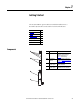
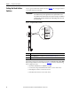
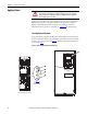
Set the option module Node Address switches (Figure 1) by rotating the switches
to the desired value for each digit.
Figure 1 - Setting Node Address Switches
The switch settings can be verified by viewing Device Parameter 06 - [Net Addr
Act] or Diagnostic Device Item number 58 (page 93
) with any of the following
drive configuration tools:
• PowerFlex 20-HIM-A6 or 20-HIM-C6S HIM
• Connected Components Workbench software, version 1.02 or later
• DriveExplorer software, version 6.01 or later
• DriveExecutive software, version 5.01 or later
IMPORTANT
Each node on the ControlNet network must have a unique address. Set the
node address before power is applied because the option module uses the
node address it detects when it first receives power. To change a node address,
you must set the new value and then remove and reapply power to (or reset)
the option module.
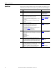
Settings Description
00 If the Node Address switches are set to ‘00’, the option module uses the value stored in Device Parameter
05 - [Net Addr Cfg] for the node address. See Setting the Node Address
on page 26.
01…99 Node address used by the option module. The default switch setting is 02.
0
5
4
9
3
8
2
7
1
6
0
5
4
9
3
8
2
7
1
6
0
5
4
9
3
8
2
7
1
6
0
5
4
9
3
8
2
7
1
6
ONES
Position
TENS
Position