User Manual PowerFlex 20-750-BNETIP BACnet/IP Option Module Firmware Revision Number 1.
Important User Information Read this document and the documents listed in the additional resources section about installation, configuration, and operation of this equipment before you install, configure, operate, or maintain this product. Users are required to familiarize themselves with installation and wiring instructions in addition to requirements of all applicable codes, laws, and standards.
Summary of Changes This manual contains new and updated information. New and Updated Information This table contains the changes made to this revision. Topic Page In Chapter 4, Table 3 in the first row AI0, corrected the drive parameter number from ‘60’ to ‘260’. 40 In Appendix D in the Segmentation Capability section, added a new checked box for ‘Segmented response accepted’. This new functionality is provided with firmware revision 1.003.
Summary of Changes Notes: 4 Rockwell Automation Publication 750COM-UM005B-EN-P - June 2014
Table of Contents Preface Conventions Used in This Manual . . . . . . . . . . . . . . . . . . . . . . . . . . . . . . . . . 9 Rockwell Automation Support . . . . . . . . . . . . . . . . . . . . . . . . . . . . . . . . . . . . . 9 Additional Resources . . . . . . . . . . . . . . . . . . . . . . . . . . . . . . . . . . . . . . . . . . . . . 10 Chapter 1 Getting Started Components . . . . . . . . . . . . . . . . . . . . . . . . . . . . . . . . . . . . . . . . . . . . . . . . . . . . . Features . . . . . .
Table of Contents Chapter 5 Troubleshooting Understanding the Status Indicators . . . . . . . . . . . . . . . . . . . . . . . . . . . . . . . PORT Status Indicator . . . . . . . . . . . . . . . . . . . . . . . . . . . . . . . . . . . . . . . . . . . MOD Status Indicator. . . . . . . . . . . . . . . . . . . . . . . . . . . . . . . . . . . . . . . . . . . . NET A Status Indicator. . . . . . . . . . . . . . . . . . . . . . . . . . . . . . . . . . . . . . . . . . . Viewing Option Module Diagnostic Items . .
Table of Contents BACnet Protocol Implementation Conformance Statement Appendix D Product Description . . . . . . . . . . . . . . . . . . . . . . . . . . . . . . . . . . . . . . . . . . . . . . BACnet Standardized Device Profile (Annex L) . . . . . . . . . . . . . . . . . . . . List all BACnet Interoperability Building Blocks Supported (Annex K) . . . . . . . . . . . . . . . . . . . . . . . . . . . . . . . . . . . . . . . . . . . . . . . . . Segmentation Capability . . . . . . . . . . . . . . . . . . . .
Table of Contents 8 Rockwell Automation Publication 750COM-UM005B-EN-P - June 2014
Preface This manual provides information about the 20-750-BNETIP BACnet/IP option module for network communication and how to use the module with PowerFlex® 750-Series drives. Conventions Used in This Manual The following conventions are used throughout this manual: • Parameter names are shown in the format Device Parameter xx - [*] or Host Parameter xx - [*]. The xx represents the parameter number. The * represents the parameter name—for example Device Parameter 01 - [Port Number].
Preface Additional Resources Resource Description Network Communication Option Module Installation Instructions, publication 750COM-IN002 Information on the installation of PowerFlex 750-Series Network Communication modules. TIA/EIA Standard PDF for CAT5e Ethernet cable at http://www.nag.ru/goodies/tia/TIA- Information about CAT5e Ethernet cable and Robotic cable. EIA-568-B.1.pdf and Allen-Bradley product website for Robotic cable at http:// ab.rockwellautomation.
Chapter 1 Getting Started The 20-750-BNETIP option module is intended for installation into a PowerFlex 750-Series drive and is used for network communication. Components Topic Page Components 11 Features 12 Understanding Parameter Types 12 Compatible Products 13 Required Equipment 13 Safety Precautions 15 Quick Start 16 ➊ Item Part Description ➊ Status Indicators Three status indicators that indicate the status of the option module and network communication.
Chapter 1 Getting Started Features The features of the option module include the following: • Captive screws to secure and ground the option module to the drive. • An IP Address Selection Jumper to set the source of the network address for the option module before applying power to the drive. The network address can come from the default network address of the option module, a DHCP server, or the option module parameter values.
Getting Started Chapter 1 You can view option module Device parameters and Host parameters with any of the following drive configuration tools: • PowerFlex 20-HIM-A6 or 20-HIM-C6S HIM—use the or key to scroll to the drive port in which the module resides, press the (Folders) key, and use the or key to scroll to the DEV PARAM or HOST PARAM folder.
Chapter 1 Getting Started ❑ Drive and option module configuration tool, such as the following: – PowerFlex 20-HIM-A6 or 20-HIM-C6S HIM – Connected Components Workbench software, version 1.02 or later Connected Components Workbench is the recommended stand-alone software tool for use with PowerFlex drives. You can obtain a free copy by: • Internet download at http://www.ab.com/support/abdrives/ webupdate/software.html • Requesting a DVD at http://www.ab.
Getting Started Safety Precautions Chapter 1 Please read the following safety precautions carefully. ATTENTION: Risk of injury or death exists. The PowerFlex drive may contain high voltages that can cause injury or death. Remove all power from the PowerFlex drive, and then verify power has been discharged before installing or removing an option module. ATTENTION: Risk of injury or equipment damage exists.
Chapter 1 Getting Started Quick Start This section is provided to help experienced users quickly start using the option module. If you are unsure how to complete a step, see the referenced chapter. Step Action See 1 Review the safety precautions for the option module. Throughout this manual 2 Verify that the PowerFlex drive is properly installed. PowerFlex 750-Series AC Drive Installation Instructions, publication 750-IN001 3 Install the option module.
Chapter 2 Installing the Option Module This chapter provides instructions for installing the option module in a PowerFlex 750-Series drive. Preparing for an Installation Topic Page Preparing for an Installation 17 Setting the IP Address Selection Jumper 18 Connecting the Option Module to the Drive 19 Connecting the Option Module to the Network 19 Applying Power 20 Commissioning the Option Module 23 Before installing the option module, verify that you have all required equipment.
Chapter 2 Installing the Option Module Setting the IP Address Selection Jumper The IP Address Selection Jumper (Figure 1) determines the source of the network address for the option module.
Installing the Option Module Connecting the Option Module to the Drive IMPORTANT Chapter 2 Remove power from the drive before installing the option module in the drive control pod. Install the option module in the PowerFlex 750-Series drive control pod in Port 4, 5, or 6. For more installation details, see the Network Communication Option Module Installation Instructions, publication 750COM-IN002, provided with the option module. See Figure 1 for an example of the option module installed in the drive.
Chapter 2 Installing the Option Module Applying Power ATTENTION: Risk of equipment damage, injury, or death exists. Unpredictable operation can occur if you fail to verify that parameter settings are compatible with your application. Verify that settings are compatible with your application before applying power to the drive. Apply power to the drive. The option module receives its power from the drive.
Installing the Option Module Chapter 2 Table 1 - Drive and Option Module Start-Up Status Indications Item Name Color Status Description Drive STS Indicator ➊ STS (Status) Green Flashing Drive ready but not running, and no faults are present. Steady Drive running, no faults are present. Flashing When running, a type 2 (non-configurable alarm condition exists – drive continues to run.
Chapter 2 Installing the Option Module Configuring and Verifying Key Drive Parameters The PowerFlex 750-Series drive can be separately configured for the control and Reference functions in various combinations. For example, you could set the drive to have its control come from a peripheral or terminal block with the Reference coming from the network. Or you could configure the drive to have its control come from the network with the Reference coming from another peripheral or terminal block.
Installing the Option Module Chapter 2 This ensures that any Reference commanded from the network can be monitored by using drive Parameter 002 - [Commanded SpdRef ]. If a problem occurs, this verification step provides the diagnostic capability to determine whether the drive/option module or the network is the cause. 4. If hard-wired discrete digital inputs are not used to control the drive, verify that all unused digital input drive parameters are set to ‘0’ (Not Used).
Chapter 2 Installing the Option Module Notes: 24 Rockwell Automation Publication 750COM-UM005B-EN-P - June 2014
Chapter 3 Configuring the Option Module This chapter provides instructions and information for setting the parameters to configure the option module.
Chapter 3 Configuring the Option Module Using the PowerFlex 20HIM-A6 or 20-HIM-C6S HIM to Access Parameters If your drive has an enhanced PowerFlex 20-HIM-A6 or 20-HIM-C6S HIM, it can be used to access parameters in the option module. 1. Display the Status screen, which is shown on HIM powerup. 2. Use the or module is installed. key to scroll to the Port in which the option 3. Press the PAR# soft key to display the Jump to Param # entry pop-up box. 4.
Configuring the Option Module Chapter 3 2. Set the value of Device Parameters 04 - [IP Addr Cfg 1] through 07 - [IP Addr Cfg 4] to a unique IP address. Default = 0.0.0.0 Stopped 0.00 Hz Edit IP Addr Cfg 1 AUTO F [IP Addr Cfg 1] [IP Addr Cfg 2] [IP Addr Cfg 3] [IP Addr Cfg 4] 0 0 << 255 ESC 255.255.255.255 ENTER 3. Reset the option module; see Resetting the Option Module on page 33. Set the Subnet Mask 1. Verify that Device Parameter 16 - [DHCP] is set to ‘0’ (Disabled). 2.
Chapter 3 Configuring the Option Module Setting the Device Instance A BACnet Device Instance number is used to identify a BACnet device over the BACnet network. A Device Instance number must be unique across all subnets and routed links. The Device Instance number could be configured depending upon the adopted network strategy. For example Figure 3 shows a Building level network having two individual floor networks through a router which allows devices on each network to share the same IP address.
Configuring the Option Module Setting the Device Port Chapter 3 Setting the Device Port enables BACnet messaging to be sent and received by the option module over the BACnet/IP network. Set Device Parameter 19 - [Device Port] to a value suitable for your application. By default, it is set to 47808. Stopped 0.
Chapter 3 Configuring the Option Module Figure 4 - Edit Fault Action HIM Screens Stopped AUTO 0.00 Hz Edit Comm Flt Action Fault 0 ESC ▲ 0 << 4 ▼ AUTO Stopped 0.00 Hz Edit Idle Flt Action Fault 0 ENTER ESC ▲ 0 << 4 ▼ ENTER Changes to these parameters take effect immediately. A reset is not required. If communication is disrupted and then is re-established, the drive will automatically receive commands over the network again.
Configuring the Option Module Setting the Comm Loss Time Chapter 3 Set Device Parameter 17 - [Comm Loss Time] to a communication loss timeout period suitable for your application. Stopped 0.00 Hz AUTO F Edit Comm Loss Time 10 0 ESC << 180 ENTER By default, the timeout is set to 10 seconds. This value can be increased or decreased. Alternatively, the value can be set to zero (0) to disable this timeout feature so that the option module does not detect a communication loss.
Chapter 3 Configuring the Option Module Setting Web Page Access By using a web browser to access the IP address set for the option module, you can view the option module web pages for information about the module, the drive, and other DPI devices connected to the drive, such as HIMs or converters. By default, the option module web pages are disabled. To enable the option module web pages, do the following. 1. Set Device Parameter 26 - [Web Enable] to ‘1’ (Enabled). Stopped 0.
Configuring the Option Module Resetting the Option Module Chapter 3 Changes to the jumper setting and some option module parameters require you to reset the option module before the new settings take effect. You can reset the option module by power cycling the drive or by using Device Parameter 03 [Reset Module]. ATTENTION: Risk of injury or equipment damage exists. If the option module is transmitting control I/O to the drive, the drive can fault when you reset the option module.
Chapter 3 Configuring the Option Module Restoring Option Module Parameters to Factory Defaults As an alternate reset method, you can restore the option module parameters by using a MEMORY folder menu item instead of using Device Parameter 03 [Reset Module] described in Resetting the Option Module on page 33. The MEMORY folder method provides two ways to restore the option module Device and Host parameters: • ALL—restores ALL option module Device and Host parameters to their factory default values.
Configuring the Option Module IMPORTANT Chapter 3 When performing a Set Defaults, the drive may detect a conflict and then not allow this function to occur. If this happens, first resolve the conflict and then repeat this Set Defaults procedure. Common reasons for a conflict include a drive running or a controller (master) in Run mode. 9. Reset the option module using Device Parameter 03 - [Reset Module] or by cycling power to the drive so that the restored parameters take effect.
Chapter 3 Configuring the Option Module Notes: 36 Rockwell Automation Publication 750COM-UM005B-EN-P - June 2014
Chapter 4 Using BACnet Services and Objects This chapter provides information about controlling and monitoring a PowerFlex 750-Series drive using BACnet objects. BACnet Services Topic Page BACnet Services 37 Understanding BACnet Objects 38 Basic Drive Operation on the Network 39 Supported BACnet Objects 40 BACnet services are used for exchanging data with a device over BACnet protocol. A BACnet server offers a set of services, which can be viewed as a set of messages (request or response).
Chapter 4 Using BACnet Services and Objects The table below provides a brief description of these services. Table 2 - BACnet Services Supported by the Option Module Property Type Name Description Object Access Services Read Property Service This service is used to read parameter values represented by BACnet objects for the PowerFlex 750-Series drive or option module.
Using BACnet Services and Objects Basic Drive Operation on the Network Chapter 4 This section describes how to operate a drive on the network using a combination of BACnet object types for basic control. ATTENTION: Control information written to the option module by a BACnet controller is volatile. That is, it will be erased by an option module reset or power cycle.
Chapter 4 Using BACnet Services and Objects Supported BACnet Objects The type of drive used on the network determines the specific BACnet objects that are supported. See Table 3 for descriptions of the BACnet objects and the drives supporting those objects. Table 3 - BACnet Object Descriptions and Supported Drives Object Name Use this Object to...
Using BACnet Services and Objects Chapter 4 Table 3 - BACnet Object Descriptions and Supported Drives (Continued) Object Name Use this Object to... Drive Parameter Number PowerFlex 750Series Drive 753 755 AV21 Mailbox1 Param Read/write any drive parameter. — ✔ ✔ AV22 Mailbox1 Value — ✔ ✔ AV23 Mailbox2 Param To read a drive parameter, write the number for the desired parameter to the Mailbox Param object, and then read the Mailbox value object.
Chapter 4 Using BACnet Services and Objects Table 3 - BACnet Object Descriptions and Supported Drives (Continued) Object Name Use this Object to... Drive Parameter Number PowerFlex 750Series Drive 753 755 BV10 Run/Stop Read/write the drive’s Run/Stop command. Turn on this object to start the drive/turn off bit to stop the drive. Logic Command Word, Bit 18 ✔ ✔ BV11 Rev/Fwd Read/write the drive’s Rev/Fwd command. Turn on this object to command the reverse direction when the drive is running.
Chapter 5 Troubleshooting This chapter provides information for diagnosing and troubleshooting potential problems with the option module and network. Understanding the Status Indicators Topic Page Understanding the Status Indicators 43 PORT Status Indicator 44 MOD Status Indicator 44 NET A Status Indicator 45 Viewing Option Module Diagnostic Items 45 Viewing and Clearing Events 47 The option module has three status indicators. They can be viewed with the drive cover removed.
Chapter 5 Troubleshooting PORT Status Indicator This red/green bicolor LED indicates the status of the option module’s connection to the drive as shown in the table below. Status Cause Corrective Action Off The option module is not powered or is not properly connected to the drive. • Securely connect and ground the option module to the drive by fully inserting it into the drive port and tightening its two captive screws to the recommended torque. • Apply power to the drive.
Troubleshooting NET A Status Indicator Chapter 5 This red/green bicolor LED indicates the status of the network connection to the option module as shown in the table below. Status Cause Corrective Actions Off The option module is not powered or is not properly connected to the network. The link is inactive. • Securely connect the option module to the drive and connect it to the network with a CAT5 cable. • Correctly connect the network cable to the option module’s RJ45 Ethernet connector.
Chapter 5 Troubleshooting Table 4 - Option Module Diagnostic Items (Continued) No. Name Description 13 14 15 16 17 18 HW Addr 1 HW Addr 2 HW Addr 3 HW Addr 4 HW Addr 5 HW Addr 6 Decimal value of each byte in the option module’s Ethernet hardware address. 19 Net Rx Pckt The number of packets received from the network. 20 Net Rx Err The present value of error packets received from the network. 21 Net Rx Terr The total number of error packets received from the network.
Troubleshooting Viewing and Clearing Events Chapter 5 The option module has an event queue to record significant events that occur in the operation of the module. When such an event occurs, an entry consisting of the event’s numeric code and a timestamp is put into the event queue. You can view the event queue with any of these drive configuration tools: • PowerFlex 20-HIM-A6 or 20-HIM-C6S HIM • Connected Components Workbench software, version 1.02 or later • DriveExplorer software, version 6.
Chapter 5 Troubleshooting Table 5 - Option Module Events (Continued) Code Event Text Description 12 DPI Host Reset The drive sent a reset event message. 13 DPI Baud 125kbps The option module detected that the drive was communicating at 125 Kbps. 14 DPI Baud 500kbps The option module detected that the drive was communicating at 500 Kbps. 15 DPI Host Invalid The option module was connected to an incompatible product.
Troubleshooting Chapter 5 Table 5 - Option Module Events (Continued) Code Event Text Description 46 Peer IO Timeout The option module has not received a Peer I/O message for longer than the Peer I/O Timeout. 47-54 Reserved — 55 DHCP Response The option module received a response to its DHCP request. 56 Email Failed The option module encountered an error attempting to send a requested e-mail message. 57 Option Card Flt Internal option module faults.
Chapter 5 Troubleshooting Notes: 50 Rockwell Automation Publication 750COM-UM005B-EN-P - June 2014
Chapter 6 Viewing Option Module Web Pages This chapter provides instructions on how to monitor the PowerFlex 750-Series drive and its BACnet/IP option module by using the module’s web interface.
Chapter 6 Viewing Option Module Web Pages 2. In the Address box, type the IP address of the option module. 3. Press ENTER. The option module web Home Page (Figure 5) appears. IMPORTANT Using the browser’s View menu, choose Refresh to always redisplay the option module Home Page while viewing any of the module’s other web pages.
Viewing Option Module Web Pages Chapter 6 Navigation Pane on Option Module Web Pages The navigation pane appears on the left side of the option module Home Page and all of the module’s other web pages. The navigation pane consists of links and link folders which can be expanded or minimized. The following table shows all navigation pane links and link folders. Navigation Pane Link/ Folder Description Home link Click this link to view the module’s Home Page (Figure 5).
Chapter 6 Viewing Option Module Web Pages Process Display Pop-up Dialog Box The Process Display pop-up dialog box dynamically shows the host drive’s information. To view this dialog box, click the ‘Process display’ link in the navigation pane. Figure 6 - Example of Process Display Pop-up Dialog Box Information Description Product Text Description of host drive. Status Status of host drive. Commanded Direction Commanded direction of host drive.
Viewing Option Module Web Pages BACnet/IP Configuration Web Page Chapter 6 The BACnet/IP Configuration web page provides information about the option module’s Ethernet settings and network activities. To view this web page, click the ‘BACnet/IP configuration’ link (highlighted in Figure 7) in the navigation pane. Figure 7 - Example of BACnet/IP Configuration Web Page Information Description IP address IP address of the option module. Subnet mask Subnet mask for the option module’s network.
Chapter 6 Viewing Option Module Web Pages Configure E-mail Notification Web Page The Configure E-mail Notification web page contains selections and data fields for configuring the option module to automatically send email messages to desired addresses when selected types of events occur. To view this web page, click the ‘Configure e-mail’ link (highlighted in Figure 8) in the navigation pane. Figure 8 - Example of Configure E-mail Notification Web Page By default, settings are not protected.
Viewing Option Module Web Pages Chapter 6 Figure 9 - Example of Selected Faults for E-mail Notification Configuration Page 2. Type the following information in their respective boxes. Information Field Description ‘IP address of…’ Type in the address of the mail server that will be used to deliver the email messages. (When the IP address is unknown, read the TIP shown below this table to determine the mail server address.
Chapter 6 Viewing Option Module Web Pages Figure 10 - DOS Dialog Box Example Showing Email Server IP Address 3. Click Save Changes. IMPORTANT After configuring E-mail Notification, we recommend protecting the settings. Otherwise the configuration can be changed anytime the web page is accessed with a browser. To protect the settings, use Device Parameter 27 - [Web Features] to set E-mail Cfg Bit 0 value to ‘0’ (Disabled).
Viewing Option Module Web Pages Device Information Pages Chapter 6 Device information pages are viewed by clicking on the respective links in the navigation pane. Web Page Description Module Information Shows module information for the respective Port device. For example, Figure 12 shows module information for the Port 0 device (host drive). Diagnostic Items Shows diagnostic item information for the respective Port device.
Chapter 6 Viewing Option Module Web Pages Figure 13 - Example of Port 0 (PowerFlex 750-Series Drive) Diagnostic Items Page Figure 14 - Example of Port 0 (PowerFlex 750-Series Drive) Fault Queue Page 60 Rockwell Automation Publication 750COM-UM005B-EN-P - June 2014
Viewing Option Module Web Pages Chapter 6 Figure 15 - Example of Port 0 (PowerFlex 750-Series Drive) Alarm Queue Page Figure 16 shows an example event queue page for the Port 4 device (BNET/IP option module).
Chapter 6 Viewing Option Module Web Pages Notes: 62 Rockwell Automation Publication 750COM-UM005B-EN-P - June 2014
Appendix A Specifications This appendix presents the specifications for the option module. Communication Electrical Mechanical Topic Page Communication 63 Electrical 63 Mechanical 63 Environmental 64 Regulatory Compliance 64 Network Protocol Data Rates Media BACnet/IP 10/100 Mbps Ethernet cable with RJ45 connector Drive Protocol Data Rates DPI 500 Kbps Consumption Drive Network 250 mA at 14 VDC supplied by the host drive None Dimensions Height Length Width 16 mm (0.
Appendix A Specifications Environmental Regulatory Compliance Temperature Operating Storage -5…65 °C (30…149 °F) -40…85 °C (-40…185 °F) Relative Humidity Operating Non-operating 5…80% non-condensing 5…95% non-condensing Shock (Operating) 15 g peak acceleration Vibration Operating Non-Operating 2 g at 55...512 Hz 5 g at 5 Hz...2 kHz Atmosphere Important: The option module must not be installed in an area where the ambient atmosphere contains volatile or corrosive gas, vapors or dust.
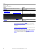
Appendix B Option Module Parameters This appendix provides information about the option module parameters. Parameter Types Topic Page Parameter Types 65 About Parameter Numbers 66 How Parameters Are Organized 66 Device Parameters 66 Host Parameters 69 The option module has two types of parameters: • Device parameters are used to configure the option module to operate on the network. • Host parameters are used to configure the option module’s various fault actions with the drive.
Appendix B Option Module Parameters About Parameter Numbers How Parameters Are Organized Each parameter set is independently and consecutively numbered. Configuration Tool Numbering Scheme • • • • Device parameters begin with parameter 01 (Device Parameter 01 - [Port Number]). Host parameters begin with parameter 33 (Host Parameter 33 - [Comm Flt Action]).
Option Module Parameters Appendix B Parameter No. Name and Description 04 05 06 07 [IP Addr Cfg 1] [IP Addr Cfg 2] [IP Addr Cfg 3] [IP Addr Cfg 4] Sets the IP address bytes for the option module’s network address when the IP Address Selection Jumper (Figure 1 on page 18) is set on Pins 1 and 2—or the jumper is missing. 255.255.255.
Appendix B Option Module Parameters Parameter No. Name and Description Details 16 [DHCP] Enables/disables the Dynamic Host Configuration Protocol server for setting the IP address of the option module. Default: Values: 17 [Comm Loss Time] Sets the communication loss timeout period in seconds. The value zero (0) disables this function.
Option Module Parameters Appendix B Parameter No. Name and Description Host Parameters Details Type: Read/Write Reset Required: No Bit Definition E-mail Cfg [Web Features] Enables/disables the web-configurable e-mail notification feature. Not Used 27 Not Used Default: Values: Not Used [Web Enable] Enables/disables the option module web pages. Not Used 26 Not Used Default: Values: Not Used [Foreign Device] Enables/disables the Foreign Device Registration.
Appendix B Option Module Parameters Parameter No. Name and Description 34 [Idle Flt Action] Sets the action that the option module and drive will take if the option module detects that the controller is in program mode or faulted. This setting is effective only if I/O that controls the drive is transmitted through the option module. When the controller is put back in Run mode, the drive will automatically receive commands over the network again.
Appendix C Logic Command/Status Words: PowerFlex 750-Series Drives This appendix presents the definitions of the Logic Command and Logic Status words that are used for PowerFlex 750-Series drives.
Appendix C Logic Command/Status Words: PowerFlex 750-Series Drives Logic Status Word Logic Bits 31 30 29 28 27 26 25 24 23 22 21 20 19 18 17 16 15 14 13 12 11 10 9 8 7 6 5 4 3 2 1 0 Command x x x x x x x x x x x x x x x x x x x x x x x x x x x x x x x x 72 Run Ready Description 0 = Not Ready to Run 1 = Ready to Run Active 0 = Not Active 1 = Active Command Direction 0 = Reverse 1 = Forward Actual Direction 0 = Reverse 1 = Forward Accelerating 0 = Not Accelerating 1 = Accelerating Deceleratin
Appendix D BACnet Protocol Implementation Conformance Statement Topic Page Product Description 73 BACnet Standardized Device Profile (Annex L) 73 List all BACnet Interoperability Building Blocks Supported (Annex K) 74 Segmentation Capability 74 Standard Object Types Supported 75 Data Link Layer Options 76 Device Address Binding 76 Networking Options 76 Network Security Options 76 Character Sets Supported 76 Date: Vendor Name: Product Name: Product Model Number: Applications Software
Appendix D BACnet Protocol Implementation Conformance Statement List all BACnet Interoperability Building Blocks Supported (Annex K) Data Sharing Data Sharing - Read Property-B (DS-RP-B) Data Sharing - Write Property-B (DS-WP-B) Data Sharing - Read Property Multiple-B (DS-RPM-B) Data Sharing - Write Property Multiple-B (DS-WPM-B) Device Management Device Management - Dynamic Device Binding-B (DM-DDB-B) Device Management - Dynamic Object Binding-B (DM-DOB-B) Device Management - Device Commun
BACnet Protocol Implementation Conformance Statement Standard Object Types Supported Appendix D The table below lists the object types supported by the Option Module. Dynamic object creation and deletion is not supported.
Appendix D BACnet Protocol Implementation Conformance Statement Data Link Layer Options Device Address Binding Is static device binding supported? (This is currently necessary for two-way communication with MS/TP slaves and certain other devices.) Yes No Networking Options Router, Clause 6 - List all routing configurations, for example, ARCNETEthernet, Ethernet-MS/TP, and so forth.
Glossary BACnet/IP BACnet is a data communication protocol for building automation and control networks. BACnet/IP is a specific type of BACnet network which allows the protocol to use TCP/IP networks. BACnet Object Any object whose properties are accessible through BACnet regardless of its particular function within the device in which it resides. Services for BACnet objects are used to access the data of PowerFlex 750-Series drives and its connected 20-750-BNETIP option module.
Glossary www.ab.com/support/abdrives/webupdate/software.html. There are no plans to provide future updates to this tool and the download is being provided ‘as-is’ for users that lost their DriveExplorer CD, or need to configure legacy products not supported by Connected Components Workbench software. DriveTools SP Software A software suite designed for running on various Microsoft Windows operating systems. This software suite provides a family of tools, including DriveExecutive software (version 3.
Glossary Hold Last When communication is disrupted (for example, a cable is disconnected), the option module and PowerFlex drive can respond by holding last. Hold last results in the drive receiving the last data received via the network connection before the disruption. If the drive was running and using the Reference from the option module, it will continue to run at the same Reference.
Glossary Logic Command/Logic Status The Logic Command is used to control the PowerFlex 750-Series drive (for example, start, stop, and direction). BACnet objects can be used to control the parameters of a PowerFlex 750-Series drive. For example, BV10 is used to change the operating state (RUN/STOP) of the drive. For a definition of BACnet objects, see Chapter 4. The Logic Status is used to monitor the PowerFlex 750-Series drive (for example, operating state and motor direction).
Glossary Status Indicators LEDs that are used to report the status of the option module, network, and drive. They are on the option module and can be viewed when the drive is powered and its cover is removed. Stop Action When communication is disrupted (for example, a cable is disconnected), the option module and drive can respond with a stop action. A stop action results in the drive receiving zero as values for Logic Command and Reference data.
Glossary Notes: 82 Rockwell Automation Publication 750COM-UM005B-EN-P - June 2014
Index A applying power to the option module 20 attentions 15 B BACnet cable 19 connector for the option module 11 data rate 63 network definition 77 specification 77 BACnet Object definition 77 for basic drive control 39 supported by the option module 40 types 38 BACnet Services supported by the option module 37 BBMD (BACnet Broadcast Management Device) 77 BBMD Cfg 1-4 Device parameters 68 BBMD Port Number Device parameter 68 bit definitions of Logic Command/Status word for PowerFlex 750-Series drives 71 b
Index G gateway 78 gateway address setting with DHCP server 18 setting with parameters 26 Gateway Cfg 1-4 Device parameters 67 H hardware address 78 HIM (Human Interface Module) accessing parameters with 26 definition 78 hold last configuring the option module for 29 definition 79 host IDs 79 Host parameters list 69-70 I idle action 79 Idle Flt Action Host parameter 70 installation applying power to the option module 20 connecting to the network 19 preparing for 17 IP Addr Cfg 1-4 Device parameters 67 IP
Index PICS (Protocol Implementation Conformance Statement) 73 ping 80 Port Number Device parameter 66 PORT status indicator locating 43 troubleshooting with 44 PowerFlex 20-HIM-A6 or 20-HIM-C6S HIM 26 PowerFlex 750-Series (Architecture Class) drives compatible with option module 13 definition 80 HIM 26 preparing for an installation 17 Q stop action 81 Subnet Cfg 1-4 Device parameters 67 subnet mask definition 81 setting with DHCP server 18 setting with parameters 26 T tools required 13 troubleshooting 4
Index 86 Rockwell Automation Publication 750COM-UM005B-EN-P - June 2014
Rockwell Automation Support Rockwell Automation provides technical information on the Web to assist you in using its products. At http://www.rockwellautomation.com/support you can find technical and application notes, sample code, and links to software service packs. You can also visit our Support Center at https://rockwellautomation.custhelp.com/ for software updates, support chats and forums, technical information, FAQs, and to sign up for product notification updates.