User Manual PowerFlex 750-Series ATEX Option Module Catalog Number 20-750-ATEX Original Instructions
Important User Information Read this document and the documents listed in the additional resources section about installation, configuration, and operation of this equipment before you install, configure, operate, or maintain this product. Users are required to familiarize themselves with installation and wiring instructions in addition to requirements of all applicable codes, laws, and standards.
Table of Contents Preface What Is the PowerFlex 750-Series ATEX Option Module? . . . . . . . . . . . . 5 Catalog Numbers for ATEX and 11-Series I/O Option Modules . . . . . . 5 Catalog Numbers for Spare Terminal Plugs . . . . . . . . . . . . . . . . . . . . . . . . . . 5 ATEX Directive 94/9/EC . . . . . . . . . . . . . . . . . . . . . . . . . . . . . . . . . . . . . . . . . . 6 Motor Requirements . . . . . . . . . . . . . . . . . . . . . . . . . . . . . . . . . . . . . . . . . . . . . . .
Table of Contents Chapter 3 Verify Operation Verify Operation . . . . . . . . . . . . . . . . . . . . . . . . . . . . . . . . . . . . . . . . . . . . . . . . . Description of Functionality . . . . . . . . . . . . . . . . . . . . . . . . . . . . . . . . . . . . . . Motors with Thermostatic Switches . . . . . . . . . . . . . . . . . . . . . . . . . . . . . . . Functional Proof Testing for Systems with Thermostat Contacts . Motors with Positive Temperature Coefficient (PTC) Devices . . . . . . .
Preface The PowerFlex® 750-Series ATEX option module and the 11-Series I/O option module for PowerFlex 750-Series AC Drives are safety system components of the equipment and protective systems intended for use in potentially explosive atmospheres (ATEX). Perform a risk assessment and safety analysis of the operating atmosphere and the ATEX system components (PowerFlex 750-Series drive, motor, ATEX option module, and 11-Series I/O option module) before you begin this ATEX installation.
Preface ATEX Directive 94/9/EC The PowerFlex 750-Series drives, together with the ATEX and 11-Series I/O option modules, are compliant safety devices under the ATEX directive 94/9/EC, and satisfy requirements for use in Group II, Category 2, (GD) applications with ATEX approved motors as described below: • Group II – The motor is installed in a potentially explosive atmosphere that is not in a mine. • Category 2 – The motor is likely to be exposed to an explosive atmosphere.
Preface Motor Requirements • The motor must be manufactured under the guidelines of the ATEX directive 94/9/EC. The motor must be installed, operated, and maintained according to the instructions of the motor manufacturer. • Only motors with nameplates marked for use on an inverter power source, and labeled for specific hazardous areas, can be used in hazardous areas on inverter (variable frequency) power.
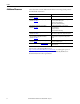
Preface Additional Resources These documents contain additional information concerning related products from Rockwell Automation. Resource Description PowerFlex 750-Series AC Drives Installation Instructions, publication 750-IN001 Provides detailed information for installing the drive.
Chapter 1 Safety Concepts Introduction The PowerFlex 750-Series ATEX option module, installed in a PowerFlex 750-Series drive equipped with an 11-Series I/O option module, provides an ATEX compliant safety function. This ATEX compliant function provides a safe turn-off for equipment installed in a potentially explosive atmosphere according to European Council Directive 94/9/EC. The overall system includes an ATEX certified motor installed in a potentially explosive atmosphere.
Chapter 1 Safety Concepts The PowerFlex 750-Series ATEX option module can be configured to support ATEX certified motors equipped with either a thermostat or a PTC-type thermal sensor. ATEX Function ATTENTION: Risk of electric shock. If a motor insulation fault occurs, high voltage can be present at the ATEX terminal block and wiring. Be sure that all drive covers are installed when power is applied to the drive.
Safety Concepts Risk Assessment Data Chapter 1 The PFD and PFH values in Table 1 were calculated based on equations in IEC 61508. This table shows the worst case calculated values for drive frames 1…10 with a proof test interval of 20 years. IMPORTANT A proof test is not defined in this user manual. A proof test interval of 20 years is used for the calculations here, signifying the product life span is 20 years. These values show the SIL1 consumption of the ATEX safety function to be approximately 30%.
Chapter 1 Safety Concepts Contact Information If Safety Option Failure Occurs 12 If you experience a failure with any safety-certified device, contact your local Rockwell Automation distributor to do the following: • Return the device to Rockwell Automation so the failure is appropriately logged for the catalog number affected and a record is made of the failure. • Request a failure analysis (if necessary) to determine the probable cause of the failure.
Chapter 2 Installation and Wiring You must follow the installation steps described in this installation and wiring section. The installation and wiring steps must be performed by qualified drive installation personnel. The PowerFlex 750-Series ATEX option module with an 11-Series I/O module are part of an ATEX safety control system.
Chapter 2 Installation and Wiring Remove the Drive Cover for Frame 1 Follow the steps in this section to remove the drive cover for frame 1. 1. Squeeze the locking tabs and pull out the bottom of the cover. 2. Pull the cover down and away from the chassis. 3. Lift the chassis cover. a. Loosen the retention screw. b. Use a screwdriver to release the chassis-cover locking tabs. c. Lift the chassis until the latch engages.
Installation and Wiring Chapter 2 Remove the Drive Cover for Frames 2…5 Follow the steps in this section to remove the drive cover for frames 2…5. 1. Squeeze the locking tabs and pull out the bottom of the cover. 2. Pull the cover down and away from the chassis. 3. Lift the human interface module (HIM) cradle. a. Loosen the retention screw. b. Lift the cradle until the latch engages.
Chapter 2 Installation and Wiring Remove the Drive Cover for Frames 6 and 7 Follow the steps in this section to remove the drive cover for frames 6 and 7. 1. Loosen the door screws. 2. Gently pry the door open and remove the door. 3. Lift the human interface module (HIM) cradle. a. Loosen the retention screw. b. Lift the cradle until the latch engages.
Installation and Wiring Chapter 2 Remove the Drive Cover for Frames 8…10 Follow the steps in this section to remove the drive cover for frames 8…10. 1. Remove the top screws. 2. Loosen the bottom screws. 3. Remove the right front cover. 4. Loosen the retention screw. 5. Lift the cradle until the latch engages.
Chapter 2 Installation and Wiring Configure the Hardware The ATEX option module can be used in two different configurations as described here: • ATEX option module and 11-Series I/O option module used without an additional safety option module • ATEX option module and 11-Series I/O option module used with an additional safety option module, such as a safe torque-off (catalog number 20-750-S) or safe speed monitor (catalog number 20-750-S1) option module S1 Switch Location ATTENTION: Hazard of electric s
Installation and Wiring Chapter 2 ATEX Option Module and 11-Series I/O Option Module without a Safety Option Module Follow these steps to configure the ATEX option module with 11-Series I/O option module for use without a safe torque-off (catalog number 20-750-S) or safe speed monitor (catalog number 20-750-S1) option module. 1. Set switch S1-1 to ON. 2. Set switch S1-2 for Thermostat mode or PTC mode.
Chapter 2 Installation and Wiring ATEX Option Module and 11-Series I/O Option Module with a Safety Option Module Follow these steps to configure the ATEX option module with 11-Series I/O option module for use with a safe torque-off (catalog number 20-750-S) or safe speed monitor (catalog number 20-750-S1) option module. 1. Set switch S1-1 to OFF. 2. Set switch S1-2 for Thermostat mode or PTC mode.
Installation and Wiring Chapter 2 Assemble the ATEX and 11-Series I/O Option Modules After the S1 switches and safety enable jumper are set for your application, join the ATEX option module with the 11-Series I/O option module. IMPORTANT Verify that the ATEX function switches are configured correctly for your application before mounting on the 11-Series I/O option module. Once the module is snapped into place, the switches are no longer accessible. 1.
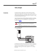
Chapter 2 Installation and Wiring Connect the Thermal Sensor Wires 20-750-ATEX Connect the thermal sensor wires to the removable terminal block of the ATEX option module. Table 2 - ATEX Terminal Designations Terminal Name Description ATEX+ ATEX- Motor protection device input. Thermostat or PTC-type device. Polarity can be ignored. ATEX input (+) ATEX input (–) ATEX+ 2 ATEX- 1 Related Parameter Parameter 41 [ATEX Sts] See Parameter 41 [ATEX Sts] on page 33.
Installation and Wiring Install the ATEX Option Module Assembly Chapter 2 Follow these steps to install the ATEX option module with 11-Series I/O option module assembly in the drive. 1. Remove power from the drive and verify that the voltage on the bus capacitors has discharged. ATTENTION: To avoid an electric shock hazard, verify that the voltage on the bus capacitors has discharged completely before performing any service.
Chapter 2 Installation and Wiring 4. Firmly press the 11-Series I/O option module edge connector into port 4 or port 5. IMPORTANT The ATEX option module mounted on an 11-Series I/O option module can be installed only in drive ports 4 or 5. 5. Tighten the top and bottom retaining screws: • Recommended torque = 0.45 N•m (4.0 lb•in) • Recommended screwdriver = T15 Hexalobular IMPORTANT 24 Do not over-tighten the retaining screws.
Installation and Wiring Chapter 2 The ATEX option module with 11-Series I/O option module can be used with the safe torque-off (catalog number 20-750-S) option module. For information about the safe torque-off option module, see the PowerFlex 750-Series Safe Torque Off User Manual, publication 750-UM002. Safe Torque-off Option Wiring WARNING: Risk of Explosion. If any changes are made to an installed system, the operation of that system must be verified.
Chapter 2 Installation and Wiring Safe Speed Monitor Option Wiring The ATEX option module with 11-Series I/O option module can be used with the safe speed monitor (catalog number 20-750-S1) option module. For information about the safe speed monitor option module, see the Safe Speed Monitor Option Module for PowerFlex 750-Series AC Drives Safety Reference Manual, publication 750-RM001. WARNING: Risk of Explosion.
Installation and Wiring Chapter 2 Operating Principle The dry contact on the 11-Series I/O option module interrupts the safe stop input channel 0 (SS_IN_CH0 pin S12) on the safe speed monitor option module. The maximum SIL capability of the ATEX function is SIL1. The maximum SIL capability of the equipment utilizing the safe speed monitor option module remains the same. Safe Speed Monitor (SSM) Configuration Requirements WARNING: Risk of Explosion.
Chapter 2 Installation and Wiring Notes: 28 Rockwell Automation Publication 750-UM003B-EN-P - July 2013
Chapter 3 Verify Operation Verify Operation Test the safety function for proper operation after initial installation and after the drive system is modified. We recommend that functional testing be performed annually during regular maintenance intervals. WARNING: Risk of Explosion. If any changes are made to an installed system, the operation of that system must be verified. These changes include installation, removal, or modification of ATEX or functional safety options.
Chapter 3 Verify Operation Functional Proof Testing for Systems with Thermostat Contacts Build a test fixture with a switch, a spare terminal plug (see Catalog Numbers for Spare Terminal Plugs on page 5), and this schematic. SW1 Follow these steps to perform the thermostat contacts functional proof test. 1. Close SW1. 2. Run the drive. 3. Open SW1. If the system is working correctly, the drive faults due to a motor over-temperature event detection. See ATEX Fault Descriptions on page 34. 4.
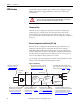
Verify Operation Chapter 3 Functional Proof Testing for Systems with PTC Devices Build a test fixture with switches, resistors, a spare terminal plug (see Catalog Numbers for Spare Terminal Plugs on page 5), and this schematic. Resistors must be at least 1/8 W and 5% tolerance. 2 kΩ 2 kΩ SW2 SW1 Over-temperature Functional Proof Test Follow these steps to perform the PTC device over-temperature functional proof test. 1. Close SW1. 2. Open SW2. 3. Run the drive. 4. Open SW1.
Chapter 3 Verify Operation Functional Proof Testing Without a Test Fixture Follow these steps to test the ATEX safety function without a test fixture. 1. Wire the ATEX daughter card to the thermal sensor in the motor. 2. Power-up the drive. 3. Verify that no faults exist. 4. Remove power from the drive and verify that the voltage on the bus capacitors has discharged.
Chapter 4 ATEX Monitoring This section describe the parameter 41 [ATEX Sts] bit functionality, the ATEX faults and configuration errors, and how to restart the drive after an over-temperature fault. Parameter 41 [ATEX Sts] appears in the 11-Series I/O file, Motor PTC group, when the ATEX option module is installed. Parameter 41 [ATEX Sts] This parameter provides the current status of the ATEX thermal sensor. If an ATEX fault occurs, the corresponding bits change.
Chapter 4 ATEX Monitoring ATEX Fault Descriptions Table 3 contains a list of ATEX-specific faults, a description, and the corrective action (where applicable). Table 3 - ATEX Faults, Descriptions, and Actions Event No. (1) Fault/Alarm Text Type xx011 PTC Over Temp An over-temperature condition has been detected in the motor, or the sensor path has been broken. xx012 PTC ShortCircuit A short circuit condition has been detected in the sensor path.
ATEX Monitoring Restart the Drive after an Over-temperature Fault Chapter 4 The drive enters a stop condition and stops current flow to the motor when an over-temperature condition is sensed in the motor. Perform these steps to restart the drive. 1. Press the Clear soft key to acknowledge the fault. The fault information is removed so that you can use the HIM. 2. Fix the condition that caused the fault. The cause must be corrected before the fault can be cleared. 3.
Chapter 4 ATEX Monitoring Notes: 36 Rockwell Automation Publication 750-UM003B-EN-P - July 2013
Appendix A Specifications and Certifications This appendix provides specifications for the PowerFlex 750-Series ATEX option module with the 11-Series I/O option module. General Specifications This table provides general specifications. Attribute Value Safety integrity level SIL 1 per IEC 61508 (see Risk Assessment Data on page 11) Conductor type Shielded twisted-pair cable, max length 150 m (492 ft) Conductor size (1) 0.3…2.5 mm2 (28…14 AWG) Strip length 6.0 mm (0.24 in.
Appendix A Specifications and Certifications Environmental Specifications This table provides environmental specifications.
Specifications and Certifications Certifications Appendix A The ATEX option module (catalog number 20-750-ATEX) together with the 11-Series I/O option module (catalog numbers 20-750-1132D 2R, 20-750-1133C-1R2T, or 20-750-1132C-2R) are certified to be in conformity with the legislation and standards listed in the table below. Certification(1) Legislation / Standard / Certificate cULus (US and Canada) (2) UL 508C (US); C22.2 No.
Appendix A Specifications and Certifications Notes: 40 Rockwell Automation Publication 750-UM003B-EN-P - July 2013
Index Numerics 11-Series I/O option module terminals screw type 37 tension clamp type 37 A additional publications 8 ATEX circuitry 10 configuration errors X Port 06 34 X Port 06 ‘Safe Speed Montr’ 34 installation example 9 status parameter 41 33 ATEX directive 94/9/EC Category 2 6 GD 6 Group II 6 ATEX option module used with a safety option module 20 used without a safety option module 19 B bus voltage test points frames 1…7 23, 32 frames 8…10 23, 32 verify discharge 23, 32 C cabling requirements therma
Index safe speed monitor parameters P44 27 P45 27 safety enable jumper 18, 19, 20 configure 20 input signal trigger 11 reaction time 11 safety configuration switch (S1-1) 18 safety function test 29 screw terminals 37 short-circuit functional proof test 31 SIL capability 25, 27 spare terminal plug kits 5 T tension clamp terminals 37 test safety function 29 test fixture PTC devices 31 thermostat contacts 30 thermal sensor cabling requirements 22 switch (S1-2) 18 wiring 22 thermostat contactsfunctional proof
Rockwell Automation Support Rockwell Automation provides technical information on the Web to assist you in using its products. At http://www.rockwellautomation.com/support you can find technical and application notes, sample code, and links to software service packs. You can also visit our Support Center at https://rockwellautomation.custhelp.com/ for software updates, support chats and forums, technical information, FAQs, and to sign up for product notification updates.