
User Manual

Specifications 5-31
Publication 198-UM001B-EN-P September 2001
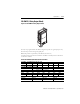
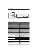
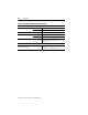
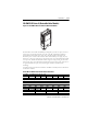
Figure 5.21 198-OW2-G4 Electrical and Application Schematic
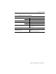
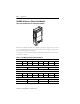
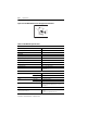
Table 5.V 198-OW2-G4 Specifications
Connector (1/2 in. x 20 Female 4-Pin)
M12 Mounting Hole 16 mm (5/8 in.)
M12 Thread 1/2 in. x 20
M12 Connector Torque 1.4 Nm (12 lb-in.)
Electrical
Module Operating Voltage Range 11…25V DC
Module Voltage Rating 24V DC
Module Current Draw 50 mA @ 24V DC
Output Voltage Rating 120V AC
Output Load Current 4 A total (Out A + Out B)
Switching Device Relay — B300, AC15, DC13
Module Isolation 132V AC working voltage
1500V AC for 1 s
3
4
1
120V AC
(
24V DC
)
PE
PE
PE
PE
Out B
Out A
L (+V)
N(0V
)
2
2
1
4
3
MALE
3
2
1
3
2
1
FEMALE
3
2
1
3
2
1
MALE
MALE
DI N V alve
T-Connector
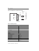
3
4
1
120V AC
(
24V DC
)
PE
PE
PE
PE
Out B
Out A
L ( +V )
N(0V
)
2
2
1
3
2
1
3
DI N V alve
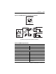
Typical Installation and Wiring
Typical Wiring for Relay Valve Module 198-OW2-G4 to Two DIN Valves