
User Manual

3-28
Publication 198-UM001B-EN-P September 2001
Each I/O module contains 4 bits (one nibble) of data. The data is packed into two modules
to a single byte of data. The Input instance (produced data) contains five bytes of status and
fault information followed by the input data for each module containing inputs. The Output
instance (consumed data) contains the output data for each module containing outputs.
The device can produce data when one of its inputs changes state. This is how the device
produces data when a Change of State (COS) connection is allocated. The device also
produces data in response to an I/O message from its master. This how the device produces
data when a Polled I/O connection is allocated. Following is an example of how the I/O
messages are formatted for the lineup shown.
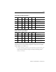
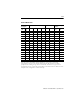
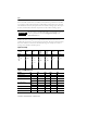
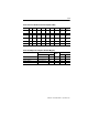
Figure 3.2 Lineup
X = Reserved
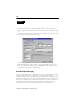
IMPORTANT
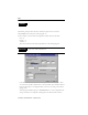
The size of the I/O produced data and I/O consumed data can be read
from the parameters located in the Configuration Group of the
Device Parameter tab.
Cat. No.
198-DNG
Cat. No.
198-OW2
Cat. No.
198-IB4
Cat. Nos.
198-IA2X,
198-OW1
Cat. Nos.
198-IB2X,
198-OB1
Cat. Nos.
198-IA2
Cat. No.
198-IB2S
Mod 0 Mod 1 Mod 2 Mod 3 Mod 4 Mod 5 Mod 6
Mod/Net Out 1 In 1 In 1 In 1 In 1 In 1
I/O Out 2 In 2 In 2 In 2 In 2 In 2
In 3 Out 1 Out 1
In 4
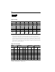
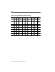
Table 3.F I/O Module Data
Module I/O Bit Bit 1 Bit 2 Bit 0
2 Output Module Output X X Out 2 Out 1
4 DC Input Module Input In 4 In 3 In 2 In 1
AC Starter Module Input X X In 2 In 1
Output X X X Out 1
DC Starter Module Input X X In 2 In 1
Output X X X Out 1
2 AC Input Input X X In 2 In 1
1 AC Input Input X X X In 1
Sensor Module Input Open Short In 2 In 1