
User Manual


3-21
Publication 198-UM001B-EN-P September 2001
Since this information is dynamically established during the power-up sequence, these
parameters can not be accessed through the standard EDS. There are two basic steps to set
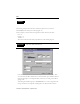
these parameters. First, map your particular configuration of modules, then use the &ODVV
,QVWDQFH(GLWRU under the 'HYLFH menu.
1. To begin configuring the parameters, you must determine the instance number of the
I/O points for your particular configuration. The instance number for any system
begins counting from the left to the right. An example of determining instance
numbers is found below.
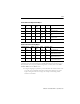
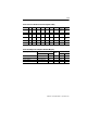
Table 3.B Discrete Output Point Object
Class ID Instance
ID
Attribute
ID
Access
Rule
Name Data Type Value
9 1 or 2 3 Get/Set Value BOOL 0 = Off
1 = On
9 1 or 2 5 Get/Set Fault
Action
BOOL 0 = Go to Fault value
1 = Hold Lasts State
9 1 or 2 6 Get/Set Fault
Value
BOOL 0 = Off
1 = On
9 1 or 2 7 Get/Set Idle
Action
BOOL 0 = Got to Idle State
1 = Hold Last State
9 1 or 2 8 Get/Set Idle
Value
BOOL 0 = Off
1 = On
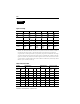
Table 3.C Presence Sensing Object
Class ID Instance
ID
Attribute
ID
Access
Rule
Name Data Type Value
14 1 or 2 1 Get Output BOOL 0 = No signal present
1 = Signal present
14 1 or 2 8 Get/Set Operate
Mode
BOOL 0 = Output attribute as specified
1 = Output Attribute inverted
14 1 or 2 122 Get Open BOOL 0 = No open condition
1 = Open condition detected
14 1 or 2 123 Get Short BOOL 0 = No short condition
1 = Short condition detected