
User Manual

DeviceNet Information A-9
Publication 198-UM001B-EN-P September 2001
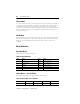
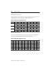
A description of each of the assemblies follows. All examples will use the following line-up as
an example.
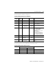
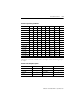
Table A.11 Input Data per Module
Module Bit 7 Bit 6 Bit 5 Bit 4 Bit 3 Bit 2 Bit 1 Bit 0
198-IB2S — — — Open Short Input 2 Input 1
198-IB4 — — — Input 4 Input 3 Input 2 Input 1
198-IB4S — — — Input 4 Input 3 Input 2 Input 1
198-IA2 — — — — — Input 2 Input 1
198-IA2-G4 — — — — — Input 2 Input 1
198-IA1-G4 9000 — — — — — — Input 1
198-OW2S — — — — — — —
198-OW2 —————— —
198-OW2-G4 — — — — — — —
198-OW2S-Q5 — — — — — — —
198-IA2XOW1 — — — — — Input 2 Input 1
198-IB2XOB1 — — — — — Input 2 Input 1
198-IB2XOW1 — — — — — Input 2 Input 1
198-IB2XOB5S — — — — — Input 2 Input 1
198-IB2XOB2S-Q5 — — — — — Input 2 Input 1
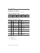
Table A.12 Assembly Description
Module Slot Module Slot
198-DNG 0 198-OW2-G4 4
198-IB2XOW1 1 198-IA2 5
198-IB2XOB1 2 198-IB2XOB5S 6
198-IB2S 3 — —