
User Manual
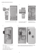

Impulse Control
Multi Function Push Button
3-phase 2-phase
Single-phase
Maintained Control
O - I Selector Switch
SUPPLY CONDUCTOR
SIZE (AWG)
BONDING CONDUCTOR
QTY. SIZE
FOR USE WITH ALLEN-BRADLEY
GROUNDING ADAPTER KIT, CAT. NO. 198-GR1
SEE APPLICABLE CODES AND LAW
FOR GROUNDING REQUIREMENTS
14
12
10
14
12
12
1
1
2
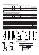
Component Selection for Three-Phase Motor Starters
Contactors 100-C and Overload Relays 193-ED / 193-EE
Current Range
230V
50Hz
400V
50Hz
500V
50Hz
690V
50Hz
200V
60Hz
230V
60Hz
460V
60Hz
575V
60Hz
100kA,
690V
100kA,
600V Components
Min
[A]
[kW] [kW] [kW] [kW] [HP] [HP] [HP] [HP]
Max
[A]
DIN Fuses
Type gL/gG
Max. Fuse
Class CC, J
Contactor
Overload
Relay
9 35 10 15 15 11...15 7 1/2 10 20 25 63 50
100-C30 00
193-ED1FD
9 38 11 18.5 18.5...20 18.5 10 10 25 30 63 50
100-C37 00
193-ED1FD
9 44 13 20...22 22...25 22 10 15 30 30 80 70
100-C43 00
193-ED1FD
To complete the cat. no., please replace with a coil voltage code.
The electronic overload relay 193-EE* can be taken as well.
Contactors 100-C and Single-Phase Overload Relays 193S-EE
Current Range
230V
50Hz
115V
60Hz
200V
60Hz
230V
60Hz
100kA,
690V
100kA,
600V Components
Min
[A]
Max
]PH[]PH[
]PH[
]Wk[
]A[
DIN Fuses
Type gL/gG
Max. Fuse
Class CC, J
Contactor
Overload
Relay
9 35 5.5 1 1/2...2 3 5 63 50
100-C30 00
193S-EETD
9 38 5.5 3 5 5 63 50
100-C37 00
193S-EETD
944 535.57 1/26360
100-C43 00
193S-EETD
To complete the cat. no., please replace with a coil voltage code.
Component Selection for Single-Phase Motor Starters
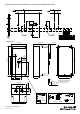
Additional components
Schematic Diagram
ytitnauQ deriuqeRnoitpircseD
Neutral Terminal
Cat. No.
Control Components required for Impulse Control
1
1
snoitangiseD lanimreT ecneuqeS htiw gnitnuoM ediS rof skcolB tcatnoC yrailixuA
100-SB10
198E-PNT
1O - I sgnikraM ,snoitcnuF 2 ,rotarepO nottuB hsuP noitcnuF-itluM
800FP-U2EFFE
Base Mounted Contact Block 1 N.C. 1
800F-BX01
Base Mounted Contact Block 1 N.O. 1
800F-BX10
Reset Push Button Operator, Marking "R" 1
800FP-F611
Control Components required for Maintained Control
Selector Switch Operator, non-illuminated, 2-position 1
800FP-SM22
Base Mounted Contact Block 1 N.O. 1
800F-BX10
Reset Push Button Operator, Marking "R" 1
800FP-F611
1
2
2
2
2
1
1
Add wires for common control. Remove if separate control is required.
(3)
¥
¥ For UL applications.
2
L1 Control voltage supplied from external source.
L1
1
96
95
97
98
L1
1
1
3
2
1
1- HAND
2- OFF
3- AUTO
A1
A2
2 WIRE
CONTROL
1 WHEN E-STOP IS USED
ILLUMINATED HOA SELECTOR SWITCH
WARNING:
Bonding between metallic conduits must be provided.
AVERTISSEMENT:
Une liaison électrique doit être assurée entre les
conduits métalliques.