
User guide
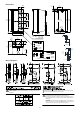

Dimensions
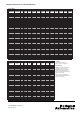
Wiring Diagrams
205
[8.08]
44.5
[1.75]
19.5
[0.77]
188
[7.41]
Ø
5
.
3
[
Ø
0
.
2
1
]
51
[2.01]
Ø
2
0
.
3
[
Ø
0
.
8
0
]
23.7
[0.94]
188
[7.41]
23.8
[0.94]
31.5
[1.24]
25.2
[0.99]
111
[4.37]
5.5
[0.22]
Ø
2
5
.
3
[
Ø
1
.
0
0
]
111
[4.37]
5.5
[0.22]
207.9
[8.19]
97.9
[3.86]
68
[2.68]
60.3
[2.38]
36.5
[1.44]
36.5
[1.44]
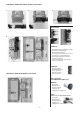
Center Marks Inside
Pilot Lights: - 140-L*: IP 54
-800FD:IP66
10
2x1...6mm²
2 x No. 14...10 AWG
Pozidriv No. 2
2.3 Nm
20 lb-in
Pozidriv No. 2
2.0 Nm
18 lb-in
(1.2 x 6.5)
188 mm Ø 5.3
7.4" 0.2" DIA
3
4
4
3
Removed when 198E-PLA installed
3
Added wires for common control. Remove if separate control is required.
4
L1 Control voltage supplied from external source.
5
5
5
5
5
5
L1
1
96
95
97
98
L1
I
I
3
2
1
1- HAND
2- OFF
3- AUTO
A1
A2
2 WIRE
CONTROL
1 When E-STOP is used
Illuminated HOA Selector Switch
WARNING:
Bonding between metallic conduits must be provided.
AVERTISSEMENT:
Une liaison électrique doit être assurée entre les conduits
métalliques.
WARNING:
The opening of the branch circuit protective device may
be an indication that a fault current has been interrupted.
To reduce the risk of re or electric shock, current-carrying parts and
other components of the controller should be examined and replaced
if damaged.
WARNING: With the mechanical latch ( ) installed or when wired for
2-wire control, a motor connected to the circuit may start automatically
when the overload relay is in the automatic reset position.