
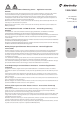
Owner's manual
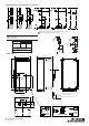

Impulse Control, Multi Function Push Button
3-phase
Maintained Control, Selector Switch < O >
Schematic Diagram for Reversing Starters
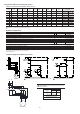
Component Selection for Reversing Starters
Contactors 100-C and Overload Relays 193-ED / 193-EE
Current
Range
230V
50Hz
400V
50Hz
500V
50Hz
690V
50Hz
200V
60Hz
230V
60Hz
460V
60Hz
575V
60Hz
100kA,
690V
100kA,
600V
Components
Min
[A] [A]
[kW] [kW] [kW] [kW] [HP] [HP] [HP] [HP]
Max DIN Fuses
Type gL/gG
Max. Fuse
Class CC, J
Contactor
Overload
Relay
0.10 0.50 0.06…0.09 0.06…0.12 0.06…0.12 0.06...0.18 23
100-C09 10
193-ED1AB
0.20 2/1...4/13/1…4/155.0…52.073.0…81.052.0…81.021.00.1 46
100-C09 10
193-ED1BB
1.0 5.0 0.18…1.1 0.37…1.5 0.55…2.2 0.75…3 1/4…3/4 1/4…1 1/2...2 3/4…3 16 20
100-C09 10
193-ED1CB
3.2 11.3 1.5…3 2.2…4 3.0…4 4 1…2 1 1/2...2 3…5 5...7 1/2 20 20
100-C09 10
193-ED1DB
3.2 15.0 4 5.5 5.5 5.5 3 3 7 1/2 10 25 20
100-C12 10
193-ED1DB
3.2 16.0 7.5 7.5 7.5 337 1/2 10 32 30
100-C16 10
193-ED1DB
5.7 5101555.50.02 35 40
100-C16 10
193-ED1EB
5.7 26.5 7.5 10…11 10…13 10 5 7 1/2 15 15 40 40
100-C23 10
193-ED1EB
To complete the cat. no., please replace with a coil voltage code.
The electronic overload relay 193-EE* can be taken as well.
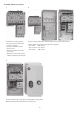
Additional components
ytitnauQ deriuqeRnoitpircseD Cat. No.
Mechanical / Electrical Interlock 1 100-MCA02
Power Wiring Kit for Reversing Starters 1
105-PW23
Control Components required for Impulse Control
Multi-Function Push Button Operator, 3 Functions, without Markings ठ1
800FP-U3F3F34
Base Mounted Contact Block 1 N.C. 1
800F-BX01
Base Mounted Contact Block 1 N.O. 2
800F-BX10
Reset Push Button Operator, Marking "R" 1
800FP-F611
Control Components required for Maintained Control
Selector Switch Operator, non-illuminated, 3-position § 1
800FP-SM32
Base Mounted Contact Block 1 N.O. 2
800F-BX10
Reset Push Button Operator, Marking "R" 1
800FP-F611
‡ For button caps with text or symbols, order the operator without cap (cat. no. 800FP-U3X ). Caps are to be ordered separately.
§
For legend plates and frames, please see catalog A116.
Neutral Terminal
1 198E-PNT
SUPPLY CONDUCTOR
SIZE (AWG)
BONDING CONDUCTOR
QTY. SIZE
FOR USE WITH ALLEN-BRADLEY
GROUNDING ADAPTER KIT, CAT. NO. 198-GR1
SEE APPLICABLE CODES AND LAW
FOR GROUNDING REQUIREMENTS
14
12
10
14
12
12
1
1
2
1
1
1
Add wires for common control. Remove if separate control is required.
(3)
¥ For UL applications.
¥
2 2
2
L1 Control voltage supplied from external source.
L1
N
1
3
5
1
3
5
6
42
64
2
K2M
F2
2
46
U
V
M
1~
K1M
SINGLE-PHASE
WARNING:
Bonding between metallic conduits must be provided.
AVERTISSEMENT:
Une liaison électrique doit être assurée entre les
conduits métalliques.