USER MANUAL BULLETIN 193 E1 Plus PROFIBUS Module CATALOG NUMBER 193-EPRB
Important User Information Solid state equipment has operational characteristics differing from those of electromechanical equipment. Safety Guidelines for the Application, Installation and Maintenance of Solid State Controls (Publication SGI-1.1 available from your local Rockwell Automation sales office or online at http://www.ab.com/manuals/gi) describes some important differences between solid state equipment and hard-wired electromechanical devices.
Table of Contents Chapter 1 Installation and Wiring Introduction . . . . . . . . . . . . . . . . . . . . . . . . . . . . . . . . . . . . . . . . . . . . . Features. . . . . . . . . . . . . . . . . . . . . . . . . . . . . . . . . . . . . . . . . . . . . . . . . Installation . . . . . . . . . . . . . . . . . . . . . . . . . . . . . . . . . . . . . . . . . . . . . . Wiring . . . . . . . . . . . . . . . . . . . . . . . . . . . . . . . . . . . . . . . . . . . . . . . . . . Dimensions. . . . . . . . . . . . . .
iv Chapter 4 Troubleshooting Introduction . . . . . . . . . . . . . . . . . . . . . . . . . . . . . . . . . . . . . . . . . . . . . PROFIBUS Modes of Operation . . . . . . . . . . . . . . . . . . . . . . . . . . . . Power-Up Mode . . . . . . . . . . . . . . . . . . . . . . . . . . . . . . . . . . . . . . Run Mode. . . . . . . . . . . . . . . . . . . . . . . . . . . . . . . . . . . . . . . . . . . . Configuration Error Mode . . . . . . . . . . . . . . . . . . . . . . . . . . . . . . Fatal Error Mode . . .
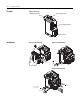
Chapter 1 Installation and Wiring Introduction The purpose of this chapter is to provide the necessary instructions to successfully install a 193-EPRB PROFIBUS Module to an E1 Plus Overload Relay and properly connect to a PROFIBUS network. ATTENTION ATTENTION ATTENTION ATTENTION ATTENTION ATTENTION To prevent electrical shock, disconnect from power source before installing or servicing. Install in suitable enclosure. Keep free from contaminants.
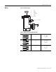
1-2 Installation and Wiring Features Figure 1.1 Features Network Status LED PROFIBUS Connector Power Supply Connector I/O Connector Installation Figure 1.2 Installation [1] Figure 1.3 Installation [2] #2 Driver 0.7 - 1.1 N . m (6 - 10 lb-in) Figure 1.4 Installation [3] 7mm (.28 in) 0.6mm X 3.5mm Blade (.02 in X .14 in Blade) 0.5 - 0.6 N . m (4.4 - 5.
Installation and Wiring Figure 1.5 Wiring Diagram 5 9 1. 2. 3. 4. 5. 6. 7. 8. 9. Housing 1 6 NC NC B-Line RTS GND BUS +5V BUS OUT NC A-Line NC SHIELD A2 ( -) 3 OUTA (B300) (20.4 - 26.4 VDC) SSV 2 A1 (+) IN2 13 14 1 Wiring 1-3 IN1 Table 1.1 Wire and Size Torque Specifications 1X 2X 24…12 AWG 24…16 AWG 5 lb.-in 1X 2X 0.2…2.5 mm2 0.25…1 mm2 0.55 N•m 1X 2X 0.2…2.5 mm2 0.2…1 mm2 0.
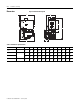
1-4 Installation and Wiring Dimensions Figure 1.6 Dimension Diagram J H A F G E K B D L C Table 1.2 Dimension Specifications Contactor Cat. No. E1 Plus Cat. No. A B C D E F G H J K L 100-C09, -C12, -C16, -C23 193*-EE_B mm (in) 67 (2.64) 148 (5.83) 85.2 (3.35) 24.5 (.96) 13.9 (.55) 35 (1.38) 60 (2.36) 86.5 (3.40) 2 (.08) 4.5 (.17) 22 (.86) 100-C30, -C37 193*EE_D mm (in) 67 (2.64) 148 (5.83) 101.2 (3.98) 24.5 (.96) 13.9 (.55) 35 (1.38) 60 (2.36) 104 (4.09) 2 (.
2 Protection Functions Introduction The purpose of this chapter is to provide detailed information regarding the protective trip and warning functions that the 193-EPRB PROFIBUS Module adds to the E1 Plus Overload Relay. In this chapter, you will find considerable mention given to parameters as they relate to these functions. For complete descriptions of the programming parameters, refer to Chapter 3 PROFIBUS Configuration.
2-2 Protection Functions event of a PROFIBUS Module failure. Settings for FLA and trip class are found directly on the E1 Plus Overload Relay. IMPORTANT The reset mode DIP switch adjustment is overridden by the PROFIBUS module parameter 11, OL Reset Mode, while the PROFIBUS module is powered. Overload Warning The PROFIBUS Module continuously monitors the E1 Plus Overload Relay's percentage of thermal utilization signal. Parameter 2,%Therm Utilized, provides this value.
Protection Functions 2-3 The PROFIBUS Module will command the E1 Plus Overload Relay to trip if all the following conditions are met: • • • • No trip currently exists Jam Protection is enabled Jam Inhibit Time has expired The motor current is greater than the Jam Trip Level for a time period greater than the Jam Trip Delay When the conditions for a jam trip are satisfied, the following will occur: • • • • Bit 2 in Parameter 3, Trip Status, will go to “1” Bit 0 in Parameter 5, Device Status, will go to
2-4 Protection Functions Underload Warning The following parameters are available for configuring the PROFIBUS Module's underload warning performance: • Parameter 17, UL Inhibit Time, allows the installer to inhibit an underload indication from occurring during the motor starting sequence. It is adjustable from 0…250 seconds. • Parameter 18, UL Warn Level, allows the installer to define the current at which the PROFIBUS Module will indicate a warning.
Protection Functions 2-5 communication idle detection helps minimize the potential damage due to uncontrolled or unmonitored applications.
2-6 Protection Functions Publication 193-UM010A-EN-P – January 2008
Chapter 3 PROFIBUS Configuration Introduction The PROFIBUS Module supports DP-V0 and DP-V1 communications. It is commissioned for a PROFIBUS network using a GSD file which contains information about parameters, profiles, I/O types, and sizes specific for this module. The GSD file for the 193-EPRB can be dowloaded from http://www.ab.com/networks/gsd/. Acyclic Parameter Access (DP-V1) The preferred way of accessing device parameters is by means of Acyclic (DP-V1) read- and write services.
3-2 PROFIBUS Configuration All changes made to parameter values, saved or not, will take effect immediately even during Data Exchange. IMPORTANT Initial Data During startup of the network, it is possible to load start-up values (loaded on each transition from offline to online) for all writable parameters by means of the User Prm Data. The PROFIBUS Module will use these settings provided that "Parameter Initialization" (User Prm Data byte #3) is set as "Enabled".
PROFIBUS Configuration 3-3 Status Register The Status Register reflects the overall status of the module as follows: Table 3.2 Status Register contents Bit 7 6 5 4 3 Function: 2 1 0 X X X X X X X X Trip Warning OutA Stat Not Used Input 1 Input 2 Save Ready Motor Curr. • Bit 0 Trip – Same functionality as bit 0 in parameter 5, Device Status. • Bit 1 Warning – Same functionality as bit 1 in parameter 5, Device Status. • Bit 2 OutA Stat – Same functionality as bit 2 in parameter 5, Device Status.
3-4 PROFIBUS Configuration Resetting to the Factory Default Values Parameter 25, Set to Defaults, allows the installer to reset all parameter settings (including trip logs) to the factory default values. IMPORTANT Resetting to factory default values also resets the node address of the PROFIBUS module to its default value of 126. Parameter Group Listing The 193-EPRB PROFIBUS Module contains six parameter groups: Table 3.
PROFIBUS Configuration Trip Status Index No. 3 This parameter provides trip identification. 1 = Trip 0 = No Trip Access Rule Read Bit 15 14 13 12 11 10 9 8 7 6 5 4 3 2 1 X X X X X X X X 14 13 12 11 10 9 8 X X X X 4 Read Size 2 bytes 7 Group Monitor Units — Min. Value — Max. Value — Default Value None Function: 6 5 4 3 2 1 0 X X X Overload Index No.
3-6 PROFIBUS Configuration Bit 15 14 13 12 11 10 9 8 7 Function: 6 5 4 3 2 1 0 X X Warning X Out A X In 1 X In 2 X X X X X X X X X X Trip Motor Current X Not Used Firmware Revision Index No. 6 This parameter reports the firmware revision of the PROFIBUS Module. Format: 0x0107 equals version 1.07 Access Rule Read Size 2 bytes Group Monitor Units — Min. Value 0 Max. Value 65535 Default Value None Serial Number Index No.
PROFIBUS Configuration Warning Enable Index No. 9 This parameter allows the installer to enable or disable the warning functions separately. All warning functions are disabled from the factory. 1 = Enabled 0 = Disabled Access Rule Read/Write Size 2 bytes Group Advanced Setup Units — Min. Value 0000000000000000 Max.
3-8 PROFIBUS Configuration Publication 193-UM010A-EN-P – January 2008 Jam Inhibit Time Index No. 13 This parameter defines the amount of time for which jam detection is inhibited during a motor starting sequence. Access Rule Read/Write Size 1 byte Group Advanced Setup Units Seconds Min. Value 0 Max. Value 250 Default Value 10 Jam Trip Delay Index No.
PROFIBUS Configuration UL Warn Level Index No. 18 This parameter sets the underload warning level. Access Rule Read/Write Size 1 byte Group Advanced Setup Units % FLA Min. Value 30 Max. Value 100 Default Value 70 3-9 Reset/Lock Group Trip Reset Index No. 19 This parameter provides the user with the capability of resetting a trip over the PROFIBUS network. After a trip is reset, the parameter automatically returns to a “Ready” state.
3-10 PROFIBUS Configuration I/O Setup Group Publication 193-UM010A-EN-P – January 2008 OutA Pr FltState Index No. 22 This parameter, in conjunction with parameter 23, defines how Output A will respond when a trip occurs. When set to “1”, Output A will continue to operate as commanded via the network. When set to “0”, Output A will open or close as determined by the setting of parameter 23. Access Rule Read/Write Size 1 byte Group I/O Setup Units — Min. Value 0 = Go To FltValue (#23) Max.
PROFIBUS Configuration OutA Pb IdlValue Index No. 27 This parameter determines the state that Output A assumes when the network is idle and parameter 26 is set to “0”. Access Rule Read/Write Size 1 byte Group I/O Setup Units — Min. Value 0 = Open Max. Value 1 = Closed Default Value 0 IN1 Assignment Index No. 28 This parameter allows the user to assign a specific function to the discrete IN1 input. Access Rule Read/Write Size 1 byte Group I/O Setup Units — Min. Value Max.
3-12 PROFIBUS Configuration Trip Log 2 Index No. 32 This parameter records the trip previous to Trip Log 1. Access Rule Read Size 2 bytes Group Trip History Units — Min. Value See Trip Status table Max. Value See Trip Status table Default Value None Trip Log 3 Index No. 33 This parameter records the trip previous to Trip Log 2. Access Rule Read Size 2 bytes Group Trip History Units — Min. Value See Trip Status table Max.
Chapter 4 Troubleshooting Introduction The purpose of this chapter is to assist in troubleshooting the E1 Plus PROFIBUS module. ATTENTION ATTENTION PROFIBUS Modes of Operation Servicing energized industrial control equipment can be hazardous. Electrical shock, burns, or unintentional actuation of controlled industrial equipment may cause death or serious injury.
4-2 Troubleshooting Configuration Error Mode In this mode, the E1 Plus PROFIBUS Module’s NETWORK STATUS LED flashes red at 1Hz. Error Type Description LED State Configuration Error Configuration fault or parameter fault Flashing Red (1Hz) Fatal Error Mode In Fatal Error Mode, the E1 Plus PROFIBUS Module’s NETWORK STATUS LED turns solid red. The overload relay continues in this state as long as the device is powered. The only way to recover from this mode is to power-cycle the module.
Troubleshooting 4-3 DP-V1 Error Codes The following table lists PROFIBUS DP-V1 error codes, possible causes, and corrective actions. Table 4.5 Troubleshooting by DP-V1 Error Code DP-V1 ErrorCode1 DP-V1 Read DP-V1 Write Possible Cause Corrective Action Read access to paramater, which could not be retrieved (e.g. EEPROM error) - X Write access filed (e.g. due to EEPROM error) - X Accessing a non-existing parameter. Correct the Index in the service request and retry.
4-4 Troubleshooting Table 4.6 Input and Output Troubleshooting Procedures (Continued) Failure Type Failure Description Corrective Action OUT A Output A does not appear to turn on (close) when commanded to do so. 1. Check the supply voltage 2. Check the programmable controller ladder logic and I/O mapping. 3. Remove the control circuit power and check for continuity across the appropriate output terminals (13/14).
Appendix A Specifications Terminal Ratings: Terminal Screw M3 Wire Cross Section See wiring diagram section Torque 0.5…0.6 N•m (4.4…5.3 lb.-in) Degree of Protection IP20 Power Supply Ratings: Rated Supply Voltage Us 24V DC Rated Operating Range Ue 20.4 - 26.4 Rated Supply Current Ie 0.1 A Maximum Surge Current at Power-Up 2.5 A Maximum Power Consumption 2.5 W Maximum Power Interruption Time 0.
A-2 Specifications Type of Inputs Current Sinking ON-State Voltage 15V DC On-State Current (turn-on) 15 mA Steady State Current 15 mA Off-State Voltage 5 VDC Off-State Current 0.5 mA Transition Voltage 5... 15 VDC Transition Current 0.5...
Specifications DP-V0 (Cyclic data exchange) Yes DP-V1 (Acyclic services) Yes DP-V2 (Acyclic services) No Set Slave Address (SSA) support Yes A-3 Jam Protection: Trip Level 150…600% FLA Trip Delay 0.1…25.0 sec. Inhibit 0…250 sec. Standards UL 508 CSA 22.2, No. 14 EN 60947-4-1 (1) Performance Criteria 1 requires the DUT (device under test) not to experience degradation or loss of performance. (2) Environment 2 - Heavy Industrial.
A-4 Specifications Publication 193-UM010A-EN-P – January 2008
Appendix B PROFIBUS Information Structure of the "Set Prm Data"-telegram During startup of the network, it is possible to force start-up values for all writable parameters through the User Prm Data. The module will use the settings provided that the "Parameter Initialization"-setting (User Prm Data byte #3) is set as "Enabled". Note that this will result in any previous settings to be replaced by the settings from the User Prm Data. Table B.5 Structure of the "Set Prm Data"-telegram Byte no.
B-2 PROFIBUS Information scaling. The GSD file for the E1 Plus PROFIBUS Module is available from the Internet at www.ab.com/networks/gsd/. Set Slave Address The PROFIBUS Module supports the Set Slave Address (SSA) service, which can be used to specify the node address from the PROFIBUS Master. If successful, the new node address will be stored in non volatile memory, replacing the previous value of parameter 35, SSA Node Address.
PROFIBUS Information PROFIBUS Identity B-3 The module has the following identity on PROFIBUS: PI Identification Number 0x0AC7 Vendor Name Allen-Bradley Model Name "193-EPRB" Identification and Maintenance (I&M) Identification & Maintenance (I&M) provides a standard way of gathering information about an I/O device. The intention is to help the end-user in maintenance of the product. The module features the following I&M records: Table B.
B-4 PROFIBUS Information Rockwell Automation Support Rockwell Automation provides technical information on the web to assist you in using its products. At http://support.rockwellautomation.com, you can find technical manuals, a knowledge base of FAQs, technical and application notes, sample code and links to software service packs, and a MySupport feature that you can customize to make the best use of these tools.
Publication 193-UM010A-EN-P — January, 2008 Copyright ©2008 Rockwell Automation, Inc. All Rights Reserved. Printed in USA.