User Manual EC4 Current Monitoring Relay Catalog Number 193-EC4
Important User Information Solid-state equipment has operational characteristics differing from those of electromechanical equipment. Safety Guidelines for the Application, Installation and Maintenance of Solid State Controls (publication SGI-1.1 available from your local Rockwell Automation sales office or online at http://www.rockwellautomation.com/literature/) describes some important differences between solid-state equipment and hard-wired electromechanical devices.
Preface Manual Objectives The purpose of this manual is to provide you with the necessary information to apply the EC4 Current Monitoring Relay with DeviceNet communications. Described in this manual are methods for installing, configuring, and troubleshooting. IMPORTANT Who Should Use This Manual Read this manual in its entirety before installing, operating, servicing, or initializing the EC4 Current Monitoring Relay.
1 To install and implement a DeviceNet network: • DeviceNet Media Design and Installation Guide Publication DNET-UM072_-EN-P IMPORTANT 4 Read the DeviceNet Media Design and Installation Guide, Publication DNET-UM072_-EN-P, in its entirety before planning and installing a DeviceNet system. If the network is not installed according to this document, unexpected operation and intermittent failures can occur.
Table of Contents Preface Manual Objectives . . . . . . . . . . . . . . . . . . . . . . . . . . . . . . . . . . . . . . . . . . . . . . . . Who Should Use This Manual . . . . . . . . . . . . . . . . . . . . . . . . . . . . . . . . . . . . . Conventions . . . . . . . . . . . . . . . . . . . . . . . . . . . . . . . . . . . . . . . . . . . . . . . . . . . . . . Reference Manuals . . . . . . . . . . . . . . . . . . . . . . . . . . . . . . . . . . . . . . . . . . . . . . . .
Table of Contents Single-Phase Full-Voltage. . . . . . . . . . . . . . . . . . . . . . . . . . . . . . . . . . . . . . External Line Current Transformer Application . . . . . . . . . . . . . . . . . . . . Current Transformer Specifications. . . . . . . . . . . . . . . . . . . . . . . . . . . . Installation Instructions. . . . . . . . . . . . . . . . . . . . . . . . . . . . . . . . . . . . . . . External Ground Fault Sensor Application . . . . . . . . . . . . . . . . . . . . . . . . .
Table of Contents Using the Node Commissioning Tool of RSNetWorx for DeviceNet. . . . . . . . . . . . . . . . . . . . . . . . . . . . . . . . . . . . . . . . . . . . . . . . 52 Produced and Consumed Assembly Configuration . . . . . . . . . . . . . . 54 Mapping to the Scanner’s Scan List. . . . . . . . . . . . . . . . . . . . . . . . . . . . . 56 Chapter 5 Programmable Parameters Introduction . . . . . . . . . . . . . . . . . . . . . . . . . . . . . . . . . . . . . . . . . . . . . . . . . . . . .
Table of Contents Chapter 9 Logic Controller Application Example with Explicit Messaging Introduction . . . . . . . . . . . . . . . . . . . . . . . . . . . . . . . . . . . . . . . . . . . . . . . . . . . . . 97 I/O Mapping . . . . . . . . . . . . . . . . . . . . . . . . . . . . . . . . . . . . . . . . . . . . . . . . . . . . 97 Explicit Messaging. . . . . . . . . . . . . . . . . . . . . . . . . . . . . . . . . . . . . . . . . . . . . . . . 99 Reading Device Status using the Parameter Object Class (0x0F) .
Table of Contents Protection . . . . . . . . . . . . . . . . . . . . . . . . . . . . . . . . . . . . . . . . . . . . . . . . . . . . . . 121 Appendix B DeviceNet Information Electronic Data Sheets . . . . . . . . . . . . . . . . . . . . . . . . . . . . . . . . . . . . . . . . . . . Product Codes . . . . . . . . . . . . . . . . . . . . . . . . . . . . . . . . . . . . . . . . . . . . . . . . . . DeviceNet Objects . . . . . . . . . . . . . . . . . . . . . . . . . . . . . . . . . . . . . . . . . . . . . .
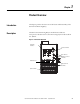
Chapter 1 Product Overview Introduction This chapter provides a brief overview of the features and functionality of the EC4 Current Monitoring Relay. Description The EC4 Current Monitoring Relay is a multi-function solid-state microprocessor-based electronic current monitoring relay for loads rated from 0.4…5000 A.
Chapter 1 Product Overview Catalog Number Explanation Figure 2 - Catalog Number Explanation 193 - EC4 Bulletin Number Type EC4 EC4 B B Current Rating (Amps) P 0.4…2.0 A 1…5 B 3…15 C 5…25 D 9…45 E 18…90 Z 9…5000 Bulletin 100 Contactor Size B D E Z C09…C23 C30…C43 C60…C85 Panel Mount, CT fed Single-/Three-Phase Operation The EC4 Current Monitoring Relay is factory-programmed to monitor three-phase current.
Product Overview Diagnostic Parameters Chapter 1 The EC4 Current Monitoring Relay allows the user to monitor the following diagnostic information over the DeviceNet network: • Device status • Trip status • Warning status • Elapsed Time • Operating Hours • History of past 5 trips and warnings Refer to Chapter 7 — Diagnostic Parameters for detailed information of these parameters. Trip Relay When the EC4 Current Monitoring Relay is in the unpowered state, the trip relay contact is open.
Chapter 1 Product Overview ATTENTION: The state of the outputs during a Protection Fault, DeviceNet Comm Fault, or a DeviceNet Comm Idle may be dependent on the OUTA or OUTB Pr FltState, Pr FltValue, Dn FltState, Dn FltValue, Dn IdlState, and Dn IdlValue programmable parameters. For details refer to the Output Setup Group section of Chapter 5 – Programmable Parameters.
Product Overview Chapter 1 Test: If Test Enable is enabled, the trip relay contact will open if the EC4 Current Monitoring Relay is in an un-tripped condition and the Test/Reset button is pressed. The Test/Reset button must be pressed for a minimum of 2 seconds to activate the test function. Reset: The trip relay contact will close if the EC4 Current Monitoring Relay is in a tripped condition, the cause of the trip is no longer present, and the Test/Reset button is pressed.
Chapter 2 Installation and Wiring Introduction This chapter provides instructions for receiving, unpacking, inspecting, and storing the EC4 Current Monitoring Relay. Installation and wiring instructions for common applications are also included. Receiving It is the responsibility of the user to thoroughly inspect the equipment before accepting the shipment from the freight company. Check the item(s) received against the purchase order.
Installation and Wiring Chapter 2 ATTENTION: The EC4 Current Monitoring Relay contains ESD (electrostatic discharge) -sensitive parts and assemblies. Static control precautions are required when installing, testing, servicing, or repairing this assembly. Component damage may result if ESD control procedures are not followed. If you are not familiar with static control procedures, refer to Allen-Bradley publication 8200-4.5.
Chapter 2 Installation and Wiring Starter Assembly Instructions Figure 3 - 100-C09…C43 Starter Assembly Instructions (for use with Cat. Nos. 193-EC_ _B and -EC_ _D) 2.
Installation and Wiring Chapter 2 Figure 4 - 100-C60…C85 Starter Assembly Instructions (for use with Cat. No.
Chapter 2 Installation and Wiring Starter Approximate Dimensions Approximate dimensions are shown in millimeters (inches). Dimensions are not intended to be used for manufacturing purposes. Figure 5 - Bulletin 109 Approximate Starter Dimensions A D2 H ØD D1 E2 B B1 E1 C F1 Table 1 - Bulletin 109 Approximate Starter Dimensions Overload Cat. No. Contactor Cat. No. Width A 193-EC_ _B 193-EC_ _D 100-C09, -C12 -C16, -C23 100-C30, -C37 193-EC_ _D 193-EC_ _E Overload Cat. No.
Installation and Wiring Chapter 2 Separate Mount Adapter Approximate Dimensions Approximate dimensions are shown in millimeters (inches). Dimensions are not intended to be used for manufacturing purposes. Figure 6 - 193-ECPM1 Panel Mount Adapter Approximate Dimensions (for use with Cat. No. 193-EC_ _B) 45 (1-25/32) 7.3 (9/32) 135 (5-5/16) 159.3 (6-17/64) 100.5 (3-31/32) ø 4.4 (11/64 ø) 6.1 (1/4) 11.
Chapter 2 Installation and Wiring Figure 8 - 193-ECPM3 Panel Mount Adapter Approximate Dimensions (for use with Cat. No. 193-EC_ _E) 71.7 (2-53/64) 60 (2-23/64) 11.4 (29/64) 150.5 (5-15/16) 155.1 (6-7/64) w/ 193-EIMD 15 (19/32) 130 (5-1/8) 77 (3 - 1/32) 5 (13/64) 22 ø 5.5 (7/32 ø) Rockwell Automation Publication 193-UM011A-EN-P - September 2010 77 (3-1/32) 131.
Installation and Wiring Chapter 2 Figure 9 - Wire Size and Torque Specifications D M E E F G K I 0 8 2 4 6 0 8 2 6 B C 4 H J L N A P Power Terminals Table 2 - Power Terminal Wire Size and Torque Specification Cat. No. Stranded/Solid AWG Flexible-Stranded with Ferrule Metric Coarse-Stranded/Solid Metric Single Conductor Torque Multiple Conductor Torque Single Conductor Torque Multiple Conductor Torque Single Conductor Torque Multiple Conductor Torque 193-EC_ _B, -EC_ _D #14...
Chapter 2 Installation and Wiring Control and DeviceNet Terminals Table 3 - Control and DeviceNet Terminal Wire Size and Torque Specification Stranded/Solid AWG Flexible-Stranded with Ferrule Metric Coarse-Stranded/Solid Metric Cat. No. Single Conductor Multiple Conductor Torque Single Conductor Multiple Conductor Torque All Types 24...12 AWG 24...16 AWG 5 lb-in Single Conductor Multiple Conductor Torque 0.2...4.0 mm2 0.2...1.5 mm2 0.55 Nm 0.25...2.5 mm2 0.5...0.75 mm2 0.
Installation and Wiring Chapter 2 Table 6 - Control Terminal Designation Terminal Designation Reference Description 95/96 Trip Relay Trip Relay IT1/IT2 — — S1/S2 — External ground fault sensor input ➊ An earth ground connection to this terminal will assist in obtaining compliance with Electromagnetic Compatibility requirements. DeviceNet Terminals The following table defines the DeviceNet connector terminal designations.
Chapter 2 Installation and Wiring Table 9 - IEC Short-Circuit Ratings Fuse Coordination Cat. No. Prospective Current Ir [A] 193-EC_ _B Maximum Voltage [V] 1,000 Conditional Short Circuit Current Iq [A] 100,000 690 193-EC_ _D 3,000 100,000 690 193-EC_ _E 5,000 100,000 690 The following table illustrates the Type I and Type II fuse coordination when used in conjunction with Bulletin 100-C contactors.
Installation and Wiring Chapter 2 Figure 10 - Three-Phase D.O.L Wiring Diagram S.C.P.D. L1 L2 L3 E3 / E3 Plus 2/T1 4/T2 6/T3 T2 T1 T3 M Single-Phase Full-Voltage The following figure illustrates the EC4 Current Monitoring Relay Typical motor connections in a single-phase full voltage application.
Chapter 2 Installation and Wiring Figure 11 - Single-Phase Full-Voltage Wiring Diagram S.C.P.D. L1 L2 E3 / E3 Plus 2/T1 4/T2 T1 6/T3 T2 M External Line Current Transformer Application IMPORTANT Parameter 27, Single/Three Ph, should be set to single-phase. IMPORTANT Traditional single-phase wiring (connecting T2 to L3) will result in a vector imbalance of current flowing through the EC4 Current Monitoring Relay. This will result in inaccurate ground fault reporting and protection.
Installation and Wiring Chapter 2 secondary current and the wiring burden. Finally, the CT shall be rated for protective relaying to accommodate the high inrush currents associated with motor startup and shall have an accuracy of ≤±2% over its normal operating range. Typical CT ratings include: ANSI (USA) CSA (Canada) IEC (Europe) Class C5 B0.
Chapter 2 Installation and Wiring Figure 13 - External CT Connection Diagrams IEC L1 L2 NEMA L3 L1 L2 L3 K1 L L1/1 L2/3 L3/5 E3 Primary Current Transformers T1/2 T2/4 T3/6 T L1/1 L2/3 L3/5 M External Ground Fault Sensor Application E3 Primary Current Transformers T1/2 T2/4 T3/6 T1 T2 T3 M EC4 Current Monitoring Relays are intended to provide ground fault protection when used with the Cat. No. 193-CBCT_ external ground fault (core balance) sensor.
Installation and Wiring Chapter 2 6. The power system may be solidly grounded or grounded through an impedance at its source as long as the impedance allows a magnitude of current to flow that is within the 20 mA…5 A operational range of the EC4 Current Monitoring Relay.
Chapter 2 Installation and Wiring Figure 17 - Control Wire Installation Catalog Number Maximum Frequency Current Turns Ratio Sensor Window I.D. Sensor Type Maximum Recommended Cable Size Ref: IEC Contactor Catalog Number Ref: NEMA Contactor Size 193-CBCT1 45 A 50/60 Hz 1000:1 19.1 mm (.75 in.) #8 AWG (10 mm2) @ 600V 100-C09…100-C37 00…2 193-CBCT2 90 A 50/60 Hz 1000:1 39.6 mm (1.56 in.) #2 AWG (35 mm2) @ 600V 100-C09…100-C85 00…3 193-CBCT3 180 A 50/60 Hz 1000:1 63.5 mm (2.50 in.
Installation and Wiring Chapter 2 Figure 19 - Cat. No. 193-CBCT2, -CBCT3 Approximate Dimensions [mm (in.)] 11.8 (.47) E A 44.5 (1.75) C 3.2 (.13) ØD 5.3 (.21) F Cat. No. B Dimensions C øD A B E F 193-CBCT2 96 (3.78) 89.6 (3.53) 48.3 (1.90) 39.6 (1.56) 54.6 (2.15) 69.9 (2.75) 193-CBCT3 122.4 (4.82) 115.9 (4.56) 59.7 (2.35) 63.5 (2.50) 54.1 (2.13) 96 (3.78) Figure 20 - Cat. No. 193-CBCT4 Approximate Dimensions [mm (in.)] 74.4 (2.93) 11.8 (.47) 56.2 (2.21) 146.8 (5.78) 74.9 (2.
Chapter 2 Installation and Wiring ATTENTION: Additional control circuit protection may be required. Refer to the applicable electrical codes. ATTENTION: Do not apply external voltage to 1T1, 1T2, or the input terminals IN 1…4. This may cause equipment damage. Full-Voltage Non-Reversing (with Network Control) Figure 21 - Full-Voltage Non-Reversing Starter Wiring Diagram (NEMA Nomenclature) Single-Phase Three-Phase S.C.P.D. S.C.P.D.
Installation and Wiring Chapter 2 External/Remote Reset (FRN 3.001 and later) To reset a trip from an external/remote location, configure one of the EC4 Current Monitoring Relay’s inputs for trip reset operation using one of parameters 83…86. Wire the input as shown in Figure 23 .
Chapter 3 Protective Trip and Warning Functions Introduction The purpose of this chapter is to provide detailed information regarding the protective trip and warning functions of the EC4 Current Monitoring Relay. In this chapter, you will find considerable mention given to programming parameters as they relate to these functions. For complete descriptions of the programming parameters, refer to Chapter 5 — Programmable Parameters.
Protective Trip and Warning Functions Chapter 3 Table 11 - Overcurrent Setting Ranges Current Range [A] 0.4…2 1…5 3…15 5…25 9…45 18…90 9…5000 Min. [A] 0.4 1 3 5 9 18 9 Max. [A] 2.5 6.25 18.75 31.25 56.25 112.5 6250 Default [A] 0.
Chapter 3 Protective Trip and Warning Functions • The TRIP/WARN LED will flash a red blinking pattern depending on which phase encountered the overcurrent – 5 red blinks for L1 overcurrent – 6 red blinks for L2 overcurrent – 7 red blinks for L3 overcurrent • Parameter 14, Trip Status, will change – Bit 4 will go to "1" for L1 overcurrent – Bit 5 will go to "1" for L2 overcurrent – Bit 6 will go to "1" for L3 overcurrent • Bit 0 in Parameter 21, Device Status, will go to "1" • The outputs will be placed in
Protective Trip and Warning Functions Chapter 3 Ground Fault Setting Range EC4 Current Monitoring Relays using the external ground fault sensor (Cat. no. 193-CBCT_) have four sensing ranges, which are selectable via the GF Sensing Range parameter. Parameter 106, GF Sensing Range (Series C and later) • 20…100 mA (For resistive loads only. For motor load information, please consult your local Rockwell Automation sales office or Allen-Bradley distributor.) • 100…500 mA • 200 mA …1.0 A • 1.0…5.
Chapter 3 Protective Trip and Warning Functions Parameter 37, GF Trip Level, allows the installer to define the ground fault current at which the EC4 Current Monitoring Relay will trip. It is adjustable from 20.0 mA…5.0 A IMPORTANT The ground fault inhibit timer starts after the maximum phase of load current transitions from 0 A to 30% of the device’s minimum FLA Setting or the GF Current is greater than or equal to 50% of the device’s minimum GF Current setting.
Protective Trip and Warning Functions IMPORTANT Undercurrent Protection Chapter 3 In EC4 Current monitoring relays, the Ground Fault warning function does not include a time delay feature. Once the GF Inhibit Time has expired, the Ground Fault warning indication is instantaneous. Motor current less than a specific level may indicate a mechanical malfunction in the installation, such as a torn conveyor belt, damaged fan blade, broken shaft, or worn tool.
Chapter 3 Protective Trip and Warning Functions Parameter 48, UL Warn Level, allows the installer to define the current at which the EC4 Current Monitoring Relay will indicate a warning. IMPORTANT The Underload Warning function does not include a time delay feature. Once the UL Inhibit Time has expired, the Underload warning indication is instantaneous.
Protective Trip and Warning Functions Chapter 3 Parameter 46, UL Trip Delay, allows the installer to define the time period that an underload condition must be present before a trip occurs. It is adjustable from 0.1…25.0 seconds. Parameter 47, UL Trip Level, allows the installer to define the current at which the EC4 Current Monitoring Relay will trip on an Underload.
Chapter 3 Protective Trip and Warning Functions IMPORTANT The Comm Fault State of OUT A and OUT B is defined by Parameter 67 (OUTA Dn FltState), Parameter 68 (OUTA Dn FltValue), Parameter 73 (OUTB Dn FltState), and Parameter 74 (OUTB Dn FltValue).
Protective Trip and Warning Functions Chapter 3 • Bit 0 of Parameter 21, Device Status, will go to “1” • The Trip Relay contact will open • The outputs will be placed in their Protection Fault State (if so programmed) IMPORTANT The Protection Fault state of OUT A and OUT B is defined by Parameter 65 (OUTA Pr FltState), Parameter 66 (OUTA Pr FltValue), Parameter 71 (OUTB Pr FltState), and Parameter 72 (OUTB Pr FltValue).
Chapter 3 Protective Trip and Warning Functions • The outputs will be placed in their Protection Fault State (if so programmed). IMPORTANT Preventive Maintenance Diagnostics The Protection Fault state of OUT A and OUT B is defined by Parameter 65 (OUTA Pr FltState), Parameter 66 (OUTA Pr FltValue), Parameter 71 (OUTB Pr FltState) and Parameter 72 (OUTB Pr FltValue).
Protective Trip and Warning Functions Chapter 3 • Starts Counter parameter is equal to or greater than the value set in the PM - # Starts parameter Upon a PM - # Starts warning, the following will occur: • The TRIP/WARN LED will flash an amber 14-blink pattern • Bit 13 in Parameter 15, Warning Status, will go to “1” • Bit 1 in Parameter 21, Device Status, will go to “1” Parameter 101, PM - # Starts, allows the installer to set a number of starts. It is adjustable from 0…65,535.
Chapter 4 DeviceNet Node Commissioning IMPORTANT The following recommendations are intended to ensure a trouble-free startup and operation: 1. Use the node commissioning tool in RSNetWorx or the E3 programming and control terminal when modifying the E3’s node address. Do not use the “General” tab found in the product window in RSNetWorx.
DeviceNet Node Commissioning Chapter 4 Figure 24 - Node Address Switches Table 13 - Node Address Setting Switch Settings Description 0…63 The node address setting is determined by the switch values when set in this range. 64…99 For switch settings in this range, the node address setting is determined by the software setting using the RSNetWorx for DeviceNet configuration tool. 99 Factory default setting.
Chapter 4 DeviceNet Node Commissioning TIP DeviceNet drivers must be configured using RSLinx prior to being available to RSNetWorx. 3. Select “OK”. 4. RSNetWorx notifies the user to upload or download devices before viewing configuration. Select “OK”. 5. RSNetWorx now browses the network and displays all of the nodes it has detected on the network.
DeviceNet Node Commissioning TIP Chapter 4 If you are using DeviceLogix functionality, you must download the EDS file from www.ab.com/networks.eds. Do the following to build and register the EDS file. 1. Right-click on the “Unrecognized Device” icon. The Register Device menu appears. 2. Select “Yes”. The EDS Wizard will appear. 3. Select “Next”. 4. Select “Create an EDS File”. 5. Select “Next”. 6. Select “Upload EDS” (see note above). 7. Select “Next”.
Chapter 4 DeviceNet Node Commissioning Figure 27 - Setting Default I/O Assembly Sizes 10. Next to the selected Polled check box, do the following: a. Type 8 in Input Size. b. Type 1 in Output Size. 11. Select “Next”. RSNetWorx uploads the EDS file from the EC4 Current Monitoring Relay. 12. To display the icon options for the node, select “Next”. 13. Select the EC4 Current Monitoring Relay icon by highlighting it and clicking “Change Icon”. 14. After selecting the desired icon, select “OK”. 15.
DeviceNet Node Commissioning Chapter 4 Figure 28 - Node Commissioning Device Solution Window 3. Select the EC4 Current Monitoring Relay located at node 63. 4. Select “OK”. The Node Commissioning screen shows Current Device Settings entries completed. It will also provide the current network baud rate in the New EC4 Current Monitoring Relay Settings area. Do not change the baud rate setting, unless you are sure it must be changed. 5. Type the node address that you want in the New Device Settings section.
Chapter 4 DeviceNet Node Commissioning Figure 29 - Node Commissioning Confirmation Window 8. To exit the node commissioning tool, select “Close”. 9. To update RSNetWorx and verify that the node address is set correctly, select “Single Pass Browse” from the Network menu. Produced and Consumed Assembly Configuration The Input and Output Assembly format for the EC4 Current Monitoring Relay is identified by the value in parameter 59 (Output Assembly) and parameter 60 (Input Assembly).
DeviceNet Node Commissioning Chapter 4 Figure 30 - I/O Assembly Settings Selection of Input and Output Assemblies (also referred to as Produced and Consumed Assemblies) define the format of I/O message data that is exchanged between the EC4 Current Monitoring Relay and other devices on the network.
Chapter 4 DeviceNet Node Commissioning Table 15 - Instance 105 – E3 Plus Default Consumed I/O Assembly Instance 103 E3 Plus Default Output Assembly Byte Bit 7 0 Bit 6 Bit 5 Bit 4 Bit 3 Remote Trip Bit 2 Bit 1 Bit 0 Fault Reset Out B Out A Choosing the size and format of the I/O data that is exchanged by the EC4 Current Monitoring Relay is done by selecting Input and Output Assembly instance numbers. Each assembly has a given size (in bytes).
DeviceNet Node Commissioning Chapter 4 Figure 31 - Editing Device I/O Parameters Rockwell Automation Publication 193-UM011A-EN-P - September 2010 57
Chapter 5 Programmable Parameters Introduction This chapter describes each programmable parameter and its function. Parameter Programming Refer to Chapter 4 — DeviceNet Node Commissioning for instructions in using RSNetworx for DeviceNet to modify parameter settings. The section, Device Parameter Programming — Input and Output Assemblies, shows an example of modifying Parameters 59 and 60.
Programmable Parameters Chapter 5 Table 16 - Parameter Group Listing Monitor Params (All Read-Only) Advanced Setup Reset / Lock DeviceNet Setup 10 GF-Current (in Amps) Trip Reset 26 (Ready/Reset 55 AutoBaudEnable (Enable/Disable) Trip) NonVol Baud Lock 56 Rate (125K, 25 Warning Enable 53 Program (Unlock/Lock) 250K, 500K Baud) Set To Inhibit Time COS Mask (Bit 35 GF 54 Defaults (0…250 s) (Ready/Reset 58 Masking) Defaults) Test Enable Assembly 36 GF Trip Delay (0…25 s) 103 (Enable/ 59 Output (0…140) Di
Chapter 5 Programmable Parameters Table 17 - Parameter Group Listing, Continued Monitor Params (All Read-Only) Advanced Setup Reset / Lock DeviceNet Setup Output Setup UC Trip Delay 115 L3 (0.1…25 s) 116 L3 UC Warn Level Inhibit Time 117 OC (0…250 s) 118 L1 OC Trip Level OC Trip Delay 119 L1 (0.1…25 s) 120 L1 OC Warn Level 121 L2 OC Trip Level OC Trip Delay 122 L2 (0.1…25 s) 123 L2 OC Warn Level 124 L3 OC Trip Level OC Trip Delay 125 L3 (0.
Programmable Parameters Advanced Setup Group TRIP ENABLE Parameter Number Access Rule This parameter allows the installer to enable Data Type or disable trip functions separately. Overload, Object Mapping Phase Loss, and Comm Fault are enabled from the factory.
Chapter 5 Programmable Parameters Bit 15 14 13 12 11 10 9 Function: 8 7 6 5 4 3 2 1 X X X X X X X X X X X X X GF INHIBIT TIME Ground Fault L1 Undercurrent L2 Undercurrent L3 Undercurrent L1 Overcurrent L2 Overcurrent L3 Overcurrent L1 Loss L2 Loss L3 Loss Comm Fault Comm Idle — PM — #Starts PM — Oper. Hours Parameter Number Access Rule This parameter defines the amount of time Data Type for which ground fault detection is inhibited Object Mapping during a motor starting sequence.
Programmable Parameters GF TRIP LEVEL This parameter sets the ground fault trip level. Parameter Number Access Rule Data Type Object Mapping 37 Get/Set USINT 2Chex-1-137 Group Units Minimum Value Maximum Value Default Value Advanced Setup Amps 0.02 5.0 2.5 GF WARN LEVEL Parameter Number Access Rule This parameter sets the ground fault warning Data Type level.
Chapter 5 Programmable Parameters IN1 ASSIGNMENT This parameter allows the user to assign a specific function to the discrete IN1 input. IN2 ASSIGNMENT This parameter allows the user to assign a specific function to the discrete IN2 input.
Programmable Parameters IN3 ASSIGNMENT This parameter allows the user to assign a specific function to the discrete IN3 input. IN4 ASSIGNMENT This parameter allows the user to assign a specific function to the discrete IN4 input.
Chapter 5 Programmable Parameters PM - # Starts Parameter Number Access Rule Data Type Object Mapping Group Units Minimum Value Maximum Value Default Value 101 Get/Set UINT 29hex-1-106 Advanced Setup — 0 65535 0 GF Warn Delay Parameter Number Access Rule This parameter allows the installer to Data Type program a time duration for which a ground fault condition must exist at the programmed Object Mapping level prior to the device providing a warning.
Programmable Parameters L1 UC Trip Level This parameter sets the under current trip level for line 1. Parameter Number Access Rule Data Type Object Mapping 108 Get/Set UINT 2Chex-1-159 2Chex-1-184 ➊ Group Units Advanced Setup 0.01 Amps 1 Amps ➊ 0.
Chapter 5 Programmable Parameters L2 UC Trip Delay This parameter allows the installer to program a time duration for which an under current condition must exist at the programmed level prior to the device tripping. L2 UC Warn Level This parameter sets the under current warning level for line 2. Parameter Number Access Rule Data Type Object Mapping 112 Get/Set USINT 2Chex-1-163 Group Units Minimum Value Maximum Value Default Value Advanced Setup 0.1 Seconds 0.1 25.0 1.
Programmable Parameters L3 UC Warn Level This parameter sets the under current warning level for line 3. Parameter Number Access Rule Data Type Object Mapping 116 Get/Set UINT 2Chex-1-167 2Chex-1-120 ➊ Group Units Advanced Setup 0.01 Amps 1 Amps ➊ 0.20 5000 Minimum Value Maximum Value Default Value Chapter 5 ➊ For Catalog Number 193-EC4ZZ OC Inhibit Time This parameter sets the time in which the over current protection is inhibited during a starting sequence.
Chapter 5 Programmable Parameters L1 OC Warn Level Parameter Number Access Rule This parameter sets the over current warning Data Type level for line 1. Object Mapping Group Units Minimum Value Maximum Value Default Value 120 Get/Set UINT 2Chex-1-171 2Chex-1-121 ➊ Advanced Setup 0.01 Amps 1 Amps ➊ 0.20 5000 ➊ For Catalog Number 193-EC4ZZ L2 OC Trip Level This parameter sets the over current trip level for line 2.
Programmable Parameters L3 OC Trip Level This parameter sets the over current trip level for line 3. Parameter Number Access Rule Data Type Object Mapping 124 Get/Set UINT 2Chex-1-175 2Chex-1-189 ➊ Group Units Advanced Setup 0.01 Amps 1 Amps ➊ 0.
Chapter 5 Programmable Parameters L1 Loss Trip Delay Reset/Lock Group 72 Parameter Number Access Rule This parameter allows the installer to Data Type program a time duration for which a loss on line 1 must exist prior to the device tripping.
Programmable Parameters PROGRAM LOCK Parameter Number Access Rule This parameter prohibits the device Data Type parameters from being altered when set to Object Mapping “Locked”. Group This parameter must be set to “Unlocked” to Units allow parameter modification.
Chapter 5 Programmable Parameters Parameter Number Access Rule Data Type Object Mapping Group Units Minimum Value NONVOL BAUD RATE This parameter allows the installer to manually set the desired baud rate. Parameter 55, AutoBaud Enable, must be disabled when using this parameter.
Programmable Parameters Chapter 5 INPUT ASSEMBLY Parameter Number Access Rule This parameter is used to select the desired Data Type input assembly. See Appendix B for a listing Object Mapping of available assemblies Group Units Minimum Value Maximum Value Default Value 60 Get/Set USINT 0xB4-1-17 DeviceNet Setup — 0 107 100 ASSY WORD0 PARAM Parameter Number Access Rule This parameter assigns the parameter value Data Type to be placed in Word 0 of Input Assembly Object Mapping 100.
Chapter 5 Programmable Parameters Output Setup Group IMPORTANT The parameters in the Output Setup Group provide great flexibility in terms of output relay(s) operation under the conditions of Protection Faults, Comm Fault, and Comm Idle. It is important, therefore, that the installer fully understands the use of these parameters, their interaction with Parameter 24, Trip Enable, and the order of priority. Order of Priority: The Out_Pr FltState parameter settings take priority over the other settings.
Programmable Parameters Chapter 5 Table 19 - Output State Matrix for Output Setup Parameters Commanded Output State Prior to Trip Out X PR FltState Setting Out X PR FltValue Setting Output State with Active Trip Last Commanded Output State during Trip Output State Following Trip Reset (before any new command) Open 0 = Go to FltValue 0 = Open Open Open Open Close Open -none - Open Open Closed Close Closed -none - Closed 1 = Closed Close Closed 1 = Ignore Fault — As Commanded As
Chapter 5 Programmable Parameters OUTA DN FLTSTATE Parameter Number Access Rule This parameter, in conjunction with Data Type Parameter 68, defines how Output A will Object Mapping respond when a DeviceNet network fault occurs. When set to “1”, Output A will hold Group the state prior to trip occurrence. When set Units to “0”, Output A will open or close as determined by the setting of Parameter 68.
Programmable Parameters OUTB PR FLTVALUE This parameter determines the state that Output B assumes when a trip occurs and Parameter 71 is set to “0”.
Chapter 5 Programmable Parameters DeviceLogix Group COMM OVERRIDE Parameter Number Access Rule This parameter is used to enable DeviceLogix Data Type programs to override normal output behavior Object Mapping in the event of a communication status change.
Programmable Parameters Parameter Number Access Rule This parameter allows the installer to select Data Type the events for which a Change-of-State Object Mapping (COS) message is produced.
Chapter 6 Current Monitoring Parameters Introduction This chapter provides information for the current monitoring parameters of the EC4 Current Monitoring Relay. Phase Current Reporting Current Range The EC4 Current Monitoring Relay utilizes a true RMS algorithm to calculate the RMS value of the current passing through phase L1, L2, and L3. The relay is capable of sensing and reporting currents ranging from 0% to 720% of the maximum current rating.
Current Monitoring Parameters Chapter 6 Table 20 - Current Reporting Summary (with indicated precision) FLA Setting Range [A] CT Ratio Min. Reporting Current [A] ➊ Max Reporting Current [A] ➋ 0.4…2.0 — 0.15 14.40 1…5 — 0.30 36.00 3…15 — 0.90 108.00 5…25 — 1.50 180.00 9…45 — 3.0 360.0 18…90 — 6.0 720.
Chapter 6 Current Monitoring Parameters Ground Fault Current Reporting Current Range The following chart illustrates the minimum and maximum reporting ground fault current values for a given ground fault current range. Table 22 - Ground Fault Current Reporting Summary Ground Fault Current Range Minimum Reporting Current ➊➌ Maximum Reporting Current ➋➌ E3 Plus Cat. No.
Current Monitoring Parameters L2 CURRENT Parameter Number Access Rule This parameter provides the L2 phase current Data Type measurement in amperes. Object Mapping Group Units Minimum Value Maximum Value Default Value L3 CURRENT Parameter Number Access Rule This parameter provides the L3 phase current Data Type measurement in amperes. Object Mapping GF CURRENT This parameter provides the ground fault current measurement in amperes.
Chapter 7 Diagnostic Parameters Introduction Monitor Group This chapter provides an overview of the diagnostic and status parameters reported by the EC4 Current Monitoring Relay. TRIP STATUS This parameter provides trip identification.
Diagnostic Parameters Parameter Number Access Rule Data Type Object Mapping Group Units Minimum Value Maximum Value Default Value WARNING STATUS This parameter provides warning identification. Bit 15 14 13 12 11 10 9 Chapter 7 15 Get WORD 0x29-1-115 Monitor — — — None Function: 8 7 6 5 4 3 2 1 X X X X X X X X X X X X X X TRIP LOG 0 This parameter records the latest trip. TRIP LOG 1 This parameter records the trip previous to Trip Log 0.
Chapter 7 Diagnostic Parameters TRIP LOG 2 This parameter records the trip previous to Trip Log 1. TRIP LOG 3 This parameter records the trip previous to Trip Log 2. TRIP LOG 4 This parameter records the trip previous to Trip Log 3. DEVICE STATUS This parameter provides status information of the EC4 Current Monitoring Relay as outlined in the table below.
Diagnostic Parameters Parameter Number Access Rule This parameter allows the installer to read Data Type the firmware revision number (FRN) of the E3 Object Mapping Overload Relay.
Chapter 7 Diagnostic Parameters Warn Log 2 Parameter Number Access Rule This parameter records the warning previous Data Type to Warn Log 1. Object Mapping Group Units Minimum Value Maximum Value Default Value 92 Get WORD 29hex-1-111 Monitor — See Warning Status Table See Warning Status Table 0 Warn Log 3 Parameter Number Access Rule This parameter records the warning previous Data Type to Warn Log 2.
Chapter 8 Trip History and Snapshot Trip and Warning History The EC4 Current Monitoring Relay with firmware revision 5.01 and higher offers the user programmable Trip History and Warning History diagnostic information. The user can select the specific trip and warning features that get written to the five record Trip History and Warning History. TripWarn History Group Trip History 0 Parameter Number Access Rule This parameter reports the latest trip Data Type written to the Trip History.
Chapter 8 Trip History and Snapshot Trip History 3 Parameter Number Access Rule This parameter reports the trip written to Data Type the Trip History previous to Trip History 2. Refer to Table 8.1 for the Trip History record Object Mapping identification. Group Units Minimum Value Maximum Value Default Value 135 Get UINT 0Fhex-87-01 TripWarn History — 0 48 — Trip History 4 Parameter Number Access Rule This parameter reports the trip written to Data Type the Trip History previous to Trip History 3.
Trip History and Snapshot Warn History 3 Parameter Number Access Rule This parameter reports the warning written Data Type to the Warning History previous to Warn Object Mapping History 2. Refer to Table 8.1 for the Warning History record identification.
Chapter 8 Trip History and Snapshot Warning History Codes Code 0 1 2 3 4 5 6 7 8 9 10 11 12 13 Type No Fault Ground Fault L1 Undercurrent L2 Undercurrent L3 Undercurrent L1 Overcurrent L2 Overcurrent L3 Overcurrent L1 Loss L2 Loss L3 Loss Comm Fault Comm Idle Config Fault 14 15 PM - # Starts PM- Oper.
Trip History and Snapshot WarnHistory Mask Parameter Number Access Rule This parameter allows the user to configure Data Type which current based protection features are written to the five record Warning History Object Mapping as outlined in the table below: Group Units 1 = Recorded Minimum Value 0 = Not Recorded Maximum Value Default Value Bit 15 14 13 12 11 10 9 143 Get/Set UINT 0Fhex-8F-01 TripWarn History — 0000000000000000 0111111111111111 0111111111111111 Function: 8 7 6 5 4 3 2 1 X X X X
Chapter 8 Trip History and Snapshot Parameter Number Access Rule Data Type Object Mapping Group Units Minimum Value Maximum Value Default Value 145 Get INT 0Fhex-91-01 Trip Snapshot Amps 0 32767 — Parameter Number Access Rule Data Type Object Mapping Group Units Minimum Value Maximum Value Default Value 146 Get INT 0Fhex-92-01 Trip Snapshot Amps 0 32767 — Parameter Number Access Rule This parameter reports the value of ground Data Type fault current at the time of the last relay Object Mapping trip.
Chapter 9 Logic Controller Application Example with Explicit Messaging Introduction This example demonstrates discrete control of the EC4 Current Monitoring Relay’s output relay and the use of the explicit messaging function for transferring parameter data to a CompactLogix L32E via a 1769-SDN DeviceNet scanner module named DNET. The selections shown are example-specific. Some changes by the user may be necessary to apply the concepts of this example to a specific application.
Chapter 9 Logic Controller Application Example with Explicit Messaging To have the CompactLogix controller energize OUT A of the EC4 Current Monitoring Relay using I/O Messaging, set Bit 0 in Word 1:O.Data[0] to a 1. OUT A should be energized. To verify that OUT A of the EC4 Current Monitoring Relay was energized, the CompactLogix controller will read the device status of the EC4 Current Monitoring Relay and place that information at Word 1:I.Data[0] with the L32E. Bit 2 identifies the state of OUT A.
Logic Controller Application Example with Explicit Messaging Chapter 9 For more information on configuring the scanlist of a DeviceNet Scanner, refer to DeviceNet Node Commissioning on page 4-48. Explicit Messaging The EC4 Current Monitoring Relay supports Explicit Messaging via DeviceNet. This allows a controller to read and write various parameters from an EC4 Current Monitoring Relay.
Chapter 9 Logic Controller Application Example with Explicit Messaging The Device Status is located in Parameter 21 within the EC4 Current Monitoring Relay.
Logic Controller Application Example with Explicit Messaging Chapter 9 Currently OUT A of the EC4 Current Monitoring Relay is energized as shown in Bit 2 in Integer_Files[0]. Reading Device Status using the Control Supervisor Object Class (0x29) In this example, a Periodic Task has been configured within the L32E to execute every 1000 msec in which a message instruction will be used to read the Device Status of the EC4 Current Monitoring Relay using the Control Supervisor Object Class.
Chapter 9 Logic Controller Application Example with Explicit Messaging – Destination: Integer_Files[1] Next, set up the communications path in the Communication tab to read data from the EC4 Current Monitoring Relay located at Node 6 by configuring the communication Path as “DNET, 2, 6” DNET - the name of the 1769-SDN DeviceNet Scanner 2 – The port number of the 1769-SDN DeviceNet Scanner 6 – The node address of the EC4 Current Monitoring Relay When finished, the MSG instruction will read the Device St
Logic Controller Application Example with Explicit Messaging Chapter 9 Currently OUT A of the EC4 Current Monitoring Relay is energized as shown in Bit 2 in Integer_Files[1]. Reading a Group of Parameters using the Status Object Class (0x0375) In this example, a Periodic Task has been configured within the L32E to execute every 1000 ms.
Chapter 9 Logic Controller Application Example with Explicit Messaging Next, set up the communications path in the Communication tab to read data from the EC4 Current Monitoring Relay located at Node 6 by configuring the communication Path as “DNET, 2, 6”.
Chapter 10 Using DeviceLogix™ Introduction DeviceLogix is a stand-alone Boolean program which resides within the EC4 Current Monitoring Relay. RSNetworx for DeviceNet is required to program the device; however, since the program is embedded in the EC4 software, no additional module is required to use this technology.
Chapter 10 Using DeviceLogix™ DeviceLogix Programming DeviceLogix has many applications and the implementation is typically only limited to the imagination of the programmer. Keep in mind that the application of DeviceLogix is only designed to handle simple logic routines. DeviceLogix is programmed using simple Boolean math operators, such as AND, OR, NOT, timers, counters, and latches. Decision making is made by combining these Boolean operations with any of the available I/O.
Using DeviceLogix™ Chapter 10 2. If programming offline, then continue to Step 3. If programming online, place the EC4 into Edit mode by selecting Edit from the Tools pull down menu or by selecting the button. Select Yes to enter Edit mode. 3. Using the left mouse button, select the Boolean OR (BOR) function block from the Move/Logical tab and drag it onto the display. 4. Using the left mouse button, select the Bit Input block and drag it to the left of the BOR function block.
Chapter 10 Using DeviceLogix™ 5. Place the cursor on the right of the Bit Input block and press the left mouse button. Draw a line from the Bit Input block to the In1 of the BOR function block and double-click the left mouse button to establish a connection. 6. Repeat steps 4 and 5 to add Input 2 of the EC4 to In2 of the BOR function block. 7. Using the left mouse button, select the Bit Output block and drag it to the right of the BOR function block.
Using DeviceLogix™ Chapter 10 8. Place the cursor on the left of the Bit Output block and press the left mouse button. Draw a line from the Bit Output block to the Out of the BOR function block and double-click the left mouse button to establish a connection. 9. Repeat steps 3 through 8 to add a second BOR function block that monitors Input 3 and 4 to control Output B of the EC4. 10. Disable Edit mode by de-selecting the Edit mode button the Tools menu.
Chapter 10 Using DeviceLogix™ 11. If programming the function block offline, exit the Function Block editor and go online with the DeviceNetwork. Download the parameters, including the DeviceLogix Function Blocks, to the EC4 and proceed to step 12. If programming the function block online, download the Function Blocks to the EC4 by selecting the Download button through the Communications menu. or A dialog box will appear when the Function Blocks are successfully downloaded to the EC4.
Chapter 11 Troubleshooting Introduction The purpose of this chapter is to assist in troubleshooting the EC4 Current Monitoring Relay using its advisory LEDs and diagnostic parameters. ATTENTION: Servicing energized industrial control equipment can be hazardous. Electrical shock, burns, or unintentional actuation of controlled industrial equipment may cause death or serious injury.
Chapter 11 Troubleshooting section of this chapter for tips associated with troubleshooting trip and warning conditions. A listing of these codes can be found on the side of the EC4 Current Monitoring Relay in addition to the table below.
Troubleshooting Chapter 11 IN 1,2,3 & 4 LEDs The amber IN1, IN2, IN3, or IN4 LED illuminates when a user-connected contact is closed. Power-Up Sequence After the EC4 Current Monitoring Relay is installed according to the guidelines specified in Chapter 2, apply power to the current monitoring relay’s DeviceNet connector. After applying power, the following sequence should occur: 1. The Trip relay should close 2.
Chapter 11 Troubleshooting If the power-up or reset is successful, the current monitoring relay will enter Run Mode. Run Mode In Run Mode, the EC4 Current Monitoring Relay will operate as a slave device to a master device. The NETWORK STATUS LED will blink green if there are no network connections established with a network master. When one or more connections are in the “established” state, the NETWORK STATUS LED will turn solid green.
Troubleshooting Chapter 11 Resetting a Trip ATTENTION: Resetting a trip will not correct the cause for the trip. Corrective action should be taken before resetting the trip. An EC4 Current Monitoring Relay trip condition can be reset by taking one of the following actions: 1. Actuating the TRIP/RESET button on the EC4 Current Monitoring Relay. 2. Setting the Fault Reset bit in the EC4 Current Monitoring Relay’s Output Assembly via the DeviceNet network. 3. Actuating a reset signal a.
Chapter 11 Troubleshooting Table 24 - Trip/Warn LED Troubleshooting Procedures Configuration 1. Parameter 27, Single/Three Ph, is set to single phase and 1. For three-phase applications, Parameter 27, Single/Three Ph, should Fault current is being sensed in phase L3 during motor operation. be set to “three-phase”. (warning) 2. FLA setting is outside the “legal” range, as determined by the 2. See Table 20 - and program the FLA setting within the range corresponding CT Ratio setting. specified.
Troubleshooting Chapter 11 Table 26 - Input and Output Troubleshooting Procedures Failure Type Failure Description Corrective Action Input 1...4 Input 1,2,3 or 4 does not appear to recognize a contact closure 1. Check the supply voltage on the DeviceNet connector. 2. If the applicable contact closes but the EC4 Current Monitoring Relay Input does not recognize the closure, check the continuity and wiring to the connected contact. 3. Check the IN 1,2,3 and 4 status LEDs.
Appendix A Specifications Electrical Specifications Table 1 - Motor/Load Ratings Terminals 1/L1, 3/L2, 5/L3, 2/T1, 4/T2, 6/T3 Rated Insulation Voltage (Ui) 690V AC Rated Operating Voltage (Ue) IEC: UL: 690V AC 600V AC Rated Impulse Voltage (Uimp) 6 kV Rated Operating Current (Ie) See Catalog Number Explanation Rated Frequency 20...
Specifications Appendix A Table 3 - Output and Trip Relay Ratings Terminals OUT A: OUT B (E3 Plus): Trip Relay: 13/14 23/24 95/96 Type of Contacts Form A SPST - NO Rated Thermal Current (Ithe) 5A Rated Insulation Voltage (Ui) 300V AC Rated Operating Voltage (Ue) 240V AC Rated Operating Current (Ie) 3 A (@120V AC), 1.5 A (@240V AC) 0.25 A (@110V DC), 0.1 A (@220V DC) Minimum Operating Current 10 mA @ 5V DC Rating Designation B300 Utilization Category AC-15 Resistive Load Rating (p.f.
Appendix A Specifications Table 4 - Input Ratings Off-State Current 0.5 mA Transition Voltage 5...15V DC Transition Current 0.5...2.0 mA Table 5 - Thermistor/PTC Input Ratings Terminals 1T1, 1T2 Type of Control Unit Mark A Maximum Number of Sensors 6 Maximum Cold Resistance of PTC Sensor Chain 1500 Ω Environmental Specifications Trip Resistance 3400 Ω ± 150 Ω Reset Resistance 1600 Ω ± 100 Ω Short-circuit Trip Resistance 25 Ω ± 10 Ω Maximum Voltage @ PTC Terminals (RPTC = 4 kΩ) 7.
Specifications Electromagnetic Compatibility Specifications Appendix A Table 7 - Electromagnetic Compatibility Specifications Electrostatic Discharge Immunity Test Level: Performance Criteria: RF Immunity Test Level: Performance Criteria: 8kV Air Discharge 6kV Contact Discharge 1 ➊➋ 10V/m 1 ➊➋ Electrical Fast Transient/Burst Immunity Test Level: Performance Criteria: Surge Immunity Test Level: 4kV (Power) 2kV (Control & Comm) 1 ➊➋ 2kV (L-E) 1kV (L-L) 1 ➊➋ Performance Criteria: Radiated Emissions Cla
Appendix A Specifications Table 9 - Protection Trip Warning Ground Fault (E3 Plus) Yes Yes Communication Fault Yes Yes Communication Idle Yes Yes Remote Trip Yes No Table 10 - Ground Fault Protection Type Core Balanced Intended Use Equipment Protection Classification (Per UL 1053) Class I Protection Range 20…100 mA 100…500 mA 200 mA…1.0 A 1.0…5.0 A 122 Trip & Warning Time Delay 0.1…25.
Appendix B DeviceNet Information Electronic Data Sheets Electronic Data Sheet (EDS) files are specially formatted ASCII files that provide all of the information necessary for a configuration tool (e.g., RSNetWorx for DeviceNet) to access and alter the parameters of a device. The EDS file contains all the parameter information of a device: number of parameters, groupings, parameter name, min, max, and default values, units, data format and scaling.
Appendix B DeviceNet Information Table 11 - DeviceNet Object Classes Identity Object – Class Code 0x01 Class Object 0x01 Identity 0x02 Message Router 0x03 DeviceNet 0x04 Assembly 0x05 Connection 0x08 Discrete Input Point 0x09 Discrete Output Point 0x0F Parameter 0x10 Parameter Group 0x29 Control Supervisor 0x2B Acknowledge Handler 0xB4 DN Interface Object 0xC2 PCP Object The following class attributes are supported for the Identity Object: Table 12 - Identity Object Class Att
DeviceNet Information Appendix B Table 14 - Identity Object Instance Attributes Attribute ID Access Rule Name Data Type Value 4 Get Revision Major Minor Structure of: USINT USINT 4 1 5 Get Status WORD Bit 0 — 0 = Not owned, 1 = Owned by master Bit 2 — 0 = Factory Defaulted, 1 = Configured Bit 8 — Minor recoverable fault Bit 9 — Minor unrecoverable fault Bit 10 — Major recoverable fault Bit 11 — Major unrecoverable fault 6 Get Serial Number UDINT Unique number for each device 7 Get Pr
Appendix B DeviceNet Information Table 17 - DeviceNet Object Instance Attributes Attribute ID Access Rule Name Data Type Value 1 Get/Set MAC ID USINT 0...63 2 Get/Set Baud Rate USINT 0 = 125 kbaud 1 = 250 kbaud 2 = 500 kbaud 5 Get Allocation Information Allocation’s Choice Byte Master’s MAC ID Structure of: BYTE USINT Allocation byte ➊ 0...
DeviceNet Information Appendix B Table 20 - Assembly Object Instance 101 Data Format (“OUT A CMD”) Byte Bit 7 Bit 6 Bit 5 Bit 4 Bit3 Bit 2 Bit 1 0 Bit 0 OutA Table 21 - Assembly Object Instance 103 Data Format (“BASIC CMD”) Byte Bit 7 Bit 6 0 Bit 5 Bit 4 Bit3 Remote Trip Bit 2 Bit 1 Fault Reset Bit 0 OutA Table 22 - Assembly Object Instance 104 Data Format (“OUTPUT CMD”) Byte Bit 7 Bit 6 Bit 5 Bit 4 Bit3 Bit 2 0 Bit 1 Bit 0 OutB OutA Table 23 - Assembly Object Instance 10
Appendix B DeviceNet Information Table 28 - Assembly Object Instance 107 Data Format (“STATUS”) Byte Bit 7 Bit 6 Bit 5 Bit 4 Bit3 0 Input4 Input3 Input2 Input1 OutB_Stat Bit 2 Bit 1 Bit 0 Warning Faulted OutA_Stat Table 29 - Assembly Object Instance 141 Data Format (“DEVICELOGIX STAT”) Byte Bit 7 Bit 6 Bit 5 Bit 4 Bit3 0 Input4 Input3 Input2 Input1 OutB_Stat Bit 2 Bit 1 Bit 0 Warning Faulted OutA_Stat 1 Network Output 7 Network Network Network Network Output 6 Output 5 Ou
DeviceNet Information Appendix B Table 32 - Instance 110 Data Link Output Assembly Attributes (“PARAM LINK CMD”) 2 Network Input 7 Network Network Network Network Input 6 Input 5 Input 4 Input 3 Network Input 2 Network Network Input 1 Input 0 3 Network Input 15 Network Network Network Network Input 14 Input 13 Input 12 Input 11 Network Input 10 Network Network Input 9 Input 8 4 Status Parameter A (low) 5 Status Parameter A (high) 6 Status Parameter B (low) 7 Status Parameter B (high) Tab
Appendix B DeviceNet Information Table 35 - Connection Object Instance 1 Attributes Attribute ID Access Rule Name Data Type Value 1 Get State USINT 0 = Nonexistent 1 = Configuring 3 = Established 4 = Timed out 2 Get Instance Type USINT 0 = Explicit message 3 Get Transport Class Trigger BYTE 0x83 (Class 3 Server) 4 Get Produced Connection ID UINT 10xxxxxx011 xxxxxx = Node address 5 Get Consumed Connection ID UINT 10xxxxxx100 xxxxxx = Node address 6 Get Initial Comm Character
DeviceNet Information Appendix B Table 36 - Connection Object Instance 2 Attributes Attribute Access Name ID Rule Data Type Value 5 Get Consumed Connection ID UINT 10xxxxxx101 xxxxxx = Node address 6 Get Initial Comm Characteristics BYTE 0x21 7 Get Produced Connection Size UINT 0…8 8 Get Consumed Connection Size UINT 0…8 9 Get/Set Expected Packet Rate UINT in ms 12 Get/Set Watchdog Action USINT 0 = Transition to timed out 1 = Auto delete 2 = Auto reset 13 Get Produced Con
Appendix B DeviceNet Information Table 37 - Connection Object Instance 4 Attributes Attribute ID Access Rule Name Data Type Value 12 Get/Set Watchdog Action USINT 0 = Transition to timed out 1 = Auto delete 2 = Auto reset 13 Get Produced Connection Path Length UINT 8 14 Get/Set Produced Connection Path EPATH 21 04 00 25 (assy. inst.) 00 30 03 15 Get Consumed Connection Path Length UINT 8 16 Get/Set Consumed Connection Path EPATH 21 04 00 25 (assy. inst.
DeviceNet Information Appendix B Table 39 - Connection Object Common Services Discrete Input Point Object – Class Code 0x08 Service Code Implemented for: Service Name Class Instance 0x05 No Yes Reset (Connection Object Only) 0x0E Yes Yes Get_Attribute_Single 0x10 No Yes Set_Attribute_Single The following class attributes are supported for the Discrete Input Object: Table 40 - Discrete Input Point Object Class Attributes Attribute ID Access Rule Name Data Type Value 1 Get Revision
Appendix B DeviceNet Information Multiple instances of the Discrete Output Point Object are supported, one instance for each general purpose discrete output on the EC4 Current Monitoring Relay. All instances will contain the following attributes: Table 44 - Discrete Output Point Object Instance Attributes Attribute ID Access Rule Name Data Type Value 3 Get/Set Value BOOL Output point value.
DeviceNet Information Appendix B Table 47 - Parameter Object Instance Attributes Attribute Access Rule ID Name Data Type 1 Get/Set (Only Get is supported for monitoring parameters) Parameter Value See Data Type & Data Size Attributes 2 Get Link Path Size USINT 3 Get Link Path BYTE Segment Type/Port Path Data Segment Address Dependent Path to specific device object attribute if applicable 4 Get Descriptor Parameter Dependent: 0000000000ab0cd0 WORD Value 08 a - Monitoring Parameter b -
Appendix B DeviceNet Information Table 48 - Parameter Object Common Services Parameter Group Object – Class Code 0x10 Service Code Implemented for: Service Name Class Instance 0x0E Yes Yes Get_Attribute_Single 0x10 No Yes Set_Attribute_Single 0x01 No Yes Get_Attributes_All 0x4B No Yes Get_Enum_String The following class attributes are supported for the Parameter Group Object: Table 49 - Parameter Group Object Class Attributes Attribute ID Access Rule Name Data Type Value 1 Get
DeviceNet Information Appendix B Table 50 - Parameter Group Object Instance 1 – Monitor Parameters Attribute ID Access Rule Name Data Type Value 17 Get 15th Parameter No. UINT 15 18 Get 16th Parameter No. UINT 16 19 Get 17th Parameter No. UINT 17 20 Get 18th Parameter No. UINT 18 21 Get 19th Parameter No. UINT 19 22 Get 20th Parameter No. UINT 20 23 Get 21st Parameter No. UINT 21 24 Get 22nd Parameter No. UINT 22 25 Get 23rd Parameter No.
Appendix B DeviceNet Information Table 52 - Parameter Group Object Instance 4 – Advanced Setup Parameters Attribute Access Name ID Rule Data Type Value 10 Get 8th Parameter No. UINT 32 11 Get 9th Parameter No. UINT 33 12 Get 10th Parameter No. UINT 34 13 Get 11th Parameter No. UINT 35 14 Get 12th Parameter No. UINT 36 15 Get 13th Parameter No. UINT 37 16 Get 14th Parameter No. UINT 38 17 Get 15th Parameter No. UINT 39 18 Get 16th Parameter No.
DeviceNet Information Appendix B Table 52 - Parameter Group Object Instance 4 – Advanced Setup Parameters Attribute Access Name ID Rule Data Type Value Parameter Name 102 105 106 Table 53 - Parameter Group Object Instance 5 – DeviceNet Setup Parameters Attribute Access Name ID Rule Data Type Value Parameter Name 1 Get Group Name String SHORT_STRIN “DNet Setup” G 2 Get Number of Members UINT 9 3 Get 1st Parameter No. UINT 55 AutoBaudEnable 4 Get 2nd Parameter No.
Appendix B DeviceNet Information Table 54 - Parameter Group Object Instance 6 – Output Setup Parameters Attribute Access Name ID Rule Data Type Value Parameter Name 9 Get 7th Parameter No. UINT 71 OutB Pr FltState 10 Get 8th Parameter No. UINT 72 OutB Pr FltValue 11 Get 9th Parameter No. UINT 73 OutB Dn FltState 12 Get 10th Parameter No. UINT 74 OutB Dn IdlValue 13 Get 11th Parameter No. UINT 75 OutB Dn IdlState 14 Get 12th Parameter No.
DeviceNet Information Appendix B Table 58 - Control Supervisor Object Instance Attributes Attribute ID Access Rule Name Data Type Value 10 Get Tripped BOOL 0 = No Fault present 1 = Fault Latched 11 Get Warning BOOL 0 = No Warning present 1 = Warning present (not latched) 12 Get/Set Fault Reset BOOL 0->1 = Trip Reset otherwise no action 13 Get Trip Code UINT ODVA Trip Code – In trip state indicates cause of trip; If not tripped, indicates cause of last trip.
Appendix B DeviceNet Information Table 58 - Control Supervisor Object Instance Attributes 142 Attribute ID Access Rule Name Data Type Value 115 Get Warning Status WORD Bit 0 = Reserved Bit 1 = Overload Bit 2 = Phase Loss Bit 3 = Ground Fault ** Bit 4 = Reserved Bit 5 = Jam Bit 6 = Underload Bit 7 = PTC ** Bit 8 = Current Imbal Bit 9 = Comm Fault Bit 10 = Comm Idle Bit 11 = Reserved Bit 12 = Config Fault Bit 13 = PM Starts Bit 14 = PM Oper Hours 116 Get Trip Log 0 WORD Last trip condition.
DeviceNet Information Appendix B Table 58 - Control Supervisor Object Instance Attributes Attribute ID Access Rule Name Data Type Value 126 Get/Set Trip Reset BOOL 0->1 = Trip Reset otherwise no action 130 Get/Set Reset Mode BOOL 0 = Manual 1 = Automatic 131 Get/Set OL Reset Level USINT %FLA 132 Get/Set Clear Queues BOOL 0->1 = Clear fault and warning queues, start counters and operating hour accumulators otherwise no action 177 Get/Set IN1 Assignment USINT 0 = Normal 1 = Trip
Appendix B DeviceNet Information Table 61 - Acknowledge Handler Object Instance Attributes Attribute ID Access Rule Name Data Type Value 1 Get/Set Acknowledge Timer UINT in milliseconds 2 Get/Set Retry Limit USINT 0 or 1 3 Get COS Producing Connection Instance UINT 4 The following common services are implemented for the Acknowledge Handler Object: Table 62 - Acknowledge Handler Object Common Services DeviceNet Interface Object – Class Code 0xB4 Service Code Implemented for: Service
DeviceNet Information Appendix B Table 63 - DeviceNet Interface Object Instance Attributes Attribute Access Name ID Rule Data Type Min/Max Defau lt Desc.
Appendix B DeviceNet Information Table 65 - ODVA Fault Codes Logic Supervisor Object CLASS CODE 0x030E Trip Code Description Trip Code Description 28 Jam 112 L3Overcurrent 60 Hardware / Config Flt 62 Non-Volatile Memory A single instance (instance 1) will be supported. The following instance attributes will be supported.
DeviceNet Information Appendix B Table 3: EC4 Status Object Instance Attributes Attribute Name Byte 0 4 I Trip / Warning 1 2 3 0 1 2 3 5 I Trip Log 4 5 6 7 8 9 0 1 6 Device Data 2 3 4 5 0 1 2 3 7 I Warning Log 4 5 6 7 8 9 9 Network Outputs 0 1 0 1 2 3 10 Trip History 4 5 6 7 8 9 Data I Trip Status I Trip Warning I Trip Log 0 I Trip Log 1 I Trip Log 2 I Trip Log 3 I Trip Log 4 Device Status Firmware Device Configuration I Warn Log 0 I Warn Log 1 I Warn Log 2 I Warn Log 3 I Warn Log 4 N
Appendix B DeviceNet Information Table 3: EC4 Status Object Instance Attributes Attribute Name Byte Data 0 Warn History 0 1 2 Warn History 1 3 11 Warning History 4 Warn History 2 5 6 Warn History 3 7 8 Warn History 4 9 0 SS L1 Current 1 2 12 Trip Snapshot SS L2 Current 3 4 SS L3 Current 5 6 SS GF Current 7 The following common services will be implemented.
Appendix C CE Compliance The EC4 Current Monitoring Relay is intended for use in a heavy industrial environment. It is CE marked for conformity to the Low Voltage Directive 73/23/EEC (as amended by 93/68/EEC), the EMC Directive 89/336/EEC (as amended by 92/31/EEC and 93/68/EEC), and the ATEX Directive 94/9/EC, when installed as described in this manual. IMPORTANT The conformity of the EC4 Current Monitoring Relay to these standards does not guarantee that an entire installation will conform.
Appendix C CE Compliance Low Voltage Directive 150 This product is tested to meet Low Voltage Directive 73/23/EEC, as amended by 93/68/EEC, by applying the following standards (in whole or in part), and as documented in a technical construction file: • EN 60947-4-1 – Low Voltage Switchgear and Control Gear; Part 4 – Contactors and Motor Starters, Section 1 – Electromechanical Contactors and Motor Starters • EN 60947-5-1 – Low Voltage Switchgear and Control Gear; Part 5 – Control Circuit Devices and Swit
Appendix D Two-Speed Applications Introduction The Series B and later EC4 Current Monitoring Relay provides Parameter 88, 2-Speed FLA Set, for use in two-speed motor applications. This appendix provides overview and guidance on the various methods the E3 Plus can be employed to protect 2-speed motors.
Appendix E Accessories Table 66 - Accessories Description Used With Cat. No.
Index Symbols Mapping 56 Trip History and Snapshot 91 TripWarn History Group 91 Warning History Codes 94 A Accessories 152 Acknowledge Handler Object 143 Advanced Setup Group 61 Advanced Setup Group, L2 UC Trip Delay 68 Advisory LEDs 111 Applications, External Control 151 Applications, Output Control 151 Assembly 18 Assembly Configuration 54 Assembly Object 126 Assy Word0 Param 75 Assy Word1 Param 75 Assy Word2 Param 75 Assy Word3 Param 75 Auto Baud Enable 73 Auto-baud 15 B Baud Rate, NonVol 74 C Catalog
Index Firmware 89 Flash Memory 15 Frequency Range 84 Functionality Specifications 121 Fuse Coordination 26 G GF Current 85 GF Inhibit Time 62 GF Sensing Range 62 GF Trip Delay 62 GF Trip Inhibit 65 GF Trip Level 63 GF Warn Delay 66 GF Warn Level 63 Ground Fault Current Reporting 84 Ground Fault Protection 38 Ground Fault Protection, Trip Inhibit 40 Ground Fault Protection, Warning 40 Ground Fault Sensor Application 30 Ground Fault Sensor Application, Power Cable Installation Instructions 30 Ground Fault S
Index Node Commissioning, DeviceNet 48 O OC Inhibit Time 69 ODVA Fault Codes 145 off-line node recovery 15 Operating Hours 13 OUT A 14 OUT A & OUT B LEDs 112 OUT A and B 14 OUT B 14 OutA DN Fltstate 78 OutA DN Fltvalue 78 OutA DN Idlstate 78 OutA DN Idlvalue 78 OutA PR Fltstate 77 OutA PR Fltvalue 77 OutB DN Fltstate 79 OutB DN Fltvalue 79 OutB DN Idlstate 79 OutB DN Idlvalue 79 OutB PR Fltstate 78 OutB PR Fltvalue 79 Output Assemblies 126 Output Assembly 74 Output Setup Group 76 Output Setup Parameters 7
Index Terminal Designations, Control Terminals 24 Terminal Designations, DeviceNet Terminals 25 Test 15 Test Enable 73 Test/Reset Button 14 Three-Phase Operation 12 Torque 23 Trip and Warning History 91 Trip Enable 36, 61 Trip History 13 Trip History 0 91 Trip History 1 91 Trip History 2 91 Trip History 3 92 Trip History 4 92 Trip History Codes 93 Trip Log 0 87 Trip Log 1 87 Trip Log 2 88 Trip Log 3 88 Trip Log 4 88 Trip Relay 13 Trip Reset 13, 72 Trip Snapshot 95 Trip Snapshot Group 95 Trip Status 86 Trip
Rockwell Automation Support Rockwell Automation provides technical information on the Web to assist you in using its products. At http://www.rockwellautomation.com/support/, you can find technical manuals, a knowledge base of FAQs, technical and application notes, sample code and links to software service packs, and a MySupport feature that you can customize to make the best use of these tools.