
User Manual

Rockwell Automation Publication 193-UM002I-EN-P - December 2011 89
Protective Trip & Warning Functions Chapter 3
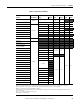
Table 22 - Protective Trip Summary
Function Factory Default
Trip Level Trip Delay Inhibit Time
➊
Range Default Range Default Range Default
Overload
Enabled
➋
Trip Class
5…30
Trip Class
10
Phase Loss
➌
0.1…25.0 s 1.0 s 0…250 s 0 s
Ground Fault (193/592-EC2)
Disabled
Internal 1…5 A 2.5 A 0.0…25.0 s 0.5 s 0…250 s 10 s
Ground Fault (193/592-EC3) External 0.02…5 A
➍ 2.5 A 0.0…25.0 s 0.5 s 0…250 s 10 s
Stall 100…600%
➎ 600% ➎ 0…250 s ➎ 10 s ➎
Jam 50…600% 250% 0.1…25.0 s 5.0 s 0…250 s 10 s
Underload 10…100% FLA
➏ 50% 0.1…25.0 s 5.0 s 0…250 s 10 s
PTC
Current Imbalance 10…100% 35% 0.1…25.0 s 5.0 s 0…250 s 10 s
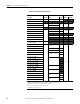
Comm Fault Enabled
Comm Idle
Disabled
Remote Trip
Voltage Input Module
Hardware Fault
➐
Undervoltage L-L ➐ 0...65535 100
0.1…25.0 s 1.0 s
0…250 s 10 s
Overvoltage L-L
➐ 0...65535 500
Voltage Unbalance
➐ 0…100 75
Phase Rotation
➐ 1…2 1
Under Frequency ➐ 0…250 57
0.1…25.0 s 1.0 s
Over Frequency
➐ 0…250 63
Under Real Power
➐
0…32767
Over Real Power ➐
Under Consumed kVAR ➐
Over Consumed kVAR ➐
Under Generated kVAR ➐ -32767…0
Over Generated kVAR ➐ -32767…0
Under Power kVA ➐ 0…32767
Over Power kVA ➐ 0…32767
Under Power Factor Lagging ➐ -100…0 -90
Over Power Factor Lagging
➐ -100…0 -95
Under Power Factor Leading
➐ 0...100 90
Over Power Factor Leading
➐ 0...100 95
➊ The inhibit time setting parameters are applicable to both the trip and warning functions.
➋ FLA Setting range and default values are dependent upon the current rating of the product. See the user manual for more information.
➌ Phase loss trip level is factory-set at a current imbalance greater than or equal to 100% and is not user-adjustable.
➍ Must use Ground Fault Sensors (Catalog Number 193-CBCT_).
➎ Stall protection is only applicable during the motor starting sequence. If any phase of current falls below the programmed Stall Trip Level, stall
protection is disabled.
➏ 50…100% for devices with FRN 1.003 and earlier.
➐ Available on 193/592-EC5 only.