
User Manual

Rockwell Automation Publication 193-UM002I-EN-P - December 2011 61
Protective Trip & Warning Functions Chapter 3
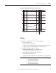
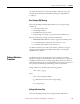
Figure 33 - PTC Sensor Characteristics per IEC-34-11-2
PTC Trip
The E3 Plus Overload Relay will trip with a PTC indication if:
• no trip currently exists,
• PTC Protection is enabled, and
• resistance across terminals 1T1 and 1T2 is either greater than the relay’s
response resistance or less than the short-circuit trip resistance.
If the E3 Plus Overload Relay trips on a PTC, the:
• TRIP/WARN LED will flash a red 8-blink pattern,
• bit 7 in Trip Status, Parameter 14, will set to “1”,
• bit 0 of Device Status, Parameter 21, will set to “1”,
• Trip Relay contact will open, and
• outputs will be placed in their Protection Fault State (if so programmed).
IMPORTANT
The Protection Fault State of OUT A and OUT B is defined by:
• OUTA Pr FltState, Parameter 65
• OUTA Pr FltValue, Parameter 66
• OUTB Pr FltState, Parameter 71
• OUTB Pr FltValue, Parameter 72
4000
1330
550
250
100
20
10
-20 °C
0 °C
TNF-20K
TNF-5K
TNF
TNF+15K
TNF+5K