
User Manual

Rockwell Automation Publication 193-UM002I-EN-P - December 2011 47
Protective Trip & Warning Functions Chapter 3
CT Ratio
Devices with the FLA setting range of 9…5000 A (Cat. No. 193-EC_ZZ) are
intended for use with primary current transformers. CT Ratio, Parameter 78,
allows the installer to identify the turns ratio of the transformers(s) in use. Each
CT Ratio selection has a corresponding valid FLA setting range, as described in
the following table.
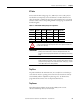
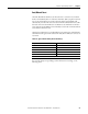
Table 18 - CT Ratio/FLA Setting Range Correspondence
Trip Class
Trip Class is defined as the maximum time (in seconds) for an overload trip to
occur when the motor’s operating current is six times its rated current. The E3
Overload Relay offers an adjustable trip class range of 5…30, which can be
programmed in increments of one via Trip Class, Parameter 29.
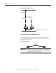
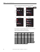
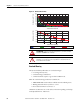
Trip Curves
The following figures illustrate the E3 Overload Relay’s time-current
characteristics for trip classes 5, 10, 20, and 30.
CT Ratio
FLA Setting
Range (A) CT Ratio
FLA Setting
Range (A) CT Ratio
FLA Setting
Range (A)
50:5 9…45 300:5 60…302 1200:5 240…1215
100:5 18…90 500:5 84…420 2500:5 450…2250
150:5 28…140 600:5 125…630 5000:5 1000…5000
200:5 42…210 800:5 172…860 —
ATTENTION: Improper configuration of the CT Ratio parameter can result
in the E3 Overload Relay reporting inaccurate motor operational data and
possible motor damage.
IMPORTANT
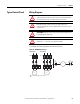
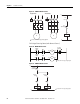
Catalog Numbers 193-EC_ _F, G, and H are assemblies that contain
primary current transformers. The device nameplate identifies the
propter CT ratio to be programmed and the associated legal FLA setting
range.
IMPORTANT
The E3 Overload Relay’s TRIP/WARN LED status indicator will flash an
amber configuration warning (13-flash sequence) when the FLA setting is
outside of the legal range of the selected CT Ratio setting (e.g., CT Ratio
set at 300:5 and the FLA Setting at 50 A).