
User Manual

34 Rockwell Automation Publication 193-UM002I-EN-P - December 2011
Chapter 2 Installation & Wiring
Typical Motor Connections
Three-Phase Direct On-Line (DOL) & Single-Phase Full Voltage
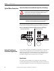
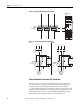
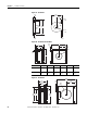
The following wiring diagram illustrates the E3 Overload Relay typical motor
connections in a three-phase DOL and Single-Phase Full Voltage applications.
Figure 13 - Wiring Diagram, Three-Phase DOL & Single-Phase Full Voltage
External Line Current
Transformer Application
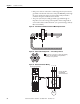
193-EC_ZZ E3 and E3 Plus Overload Relays are designed for use with separately
mounted, customer-supplied, line current transformers (CTs) as required in
higher-current applications. The FLA setting range is 9…5000 A for these units
with a legal setting range per current transformer. CT Ratio, Parameter 78, is
provided for setting the current transformer ratio to be installed.
Specifications
The 193-EC_ZZ Overload Relays are intended for use with CTs having a
secondary current rating of 5 A. The installer shall (1) provide one CT for each
motor phase and shall (2) connect the CT’s secondary leads to the appropriate E3
ATTENTION: When working on energized circuits, DO NOT rely on
voltage and current information provided by the E3 and E3 Plus Overload
Relay for personal safety. Always use a portable voltage or current
measurement device to measure the signal locally.
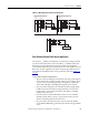
IMPORTANT
Single/Three Ph, Parameter 27, should be set to single-phase.
IMPORTANT
Traditional single-phase wiring connecting T2 to L3 will result in a vector
imbalance of current flowing through the E3 Plus Overload Relay. This
will result in inaccurate ground fault reporting and protection.
L1
2/T1
4/T2
6/T3
M
T1
Three-Phase Direct-On-Line
Single-Phase Full-Voltage
T2
L2
E3/E3 Plus
L1 L2
Voltage Input Module
(For 193/592-EC5 only)
E3/E3Plus
L1
2/T1
4/T2
6/T3
M
T1
T2
T3
S.C.P.D.
L2
L3
L1
L2
L3
Voltage Input Module
(For 193/592-EC5 only)
S.C.P.D.