
User Manual

30 Rockwell Automation Publication 193-UM002I-EN-P - December 2011
Chapter 2 Installation & Wiring
• The earth ground terminal of the E3 Overload Relay shall be connected to
a solid earth ground via a low-impedance connection.
• Installations employing an external ground fault sensor shall ground the
cable shield at the sensor with no connection made at the E3 Plus Overload
Relay.
• The PTC thermistor cable shield shall be grounded at the E3 Plus
Overload Relay with no connection made at the opposite end.
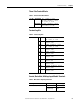
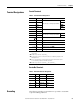
Short-Circuit Ratings
The E3 Overload Relay is suitable for use on circuits capable of delivering not
more than the RMS symmetrical amperes listed in the following tables.
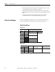
Short-Circuit Ratings
Table 10 - UL
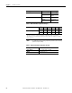
Table 11 - IEC
Cat. No. Maximum
193-EC_ _ 592-EC_ _ Available Fault Current [A] Voltage [V]
B T 5,000 600
DC
ED10,000
F
G 18,000
H 42,000
Z 5,000
Cat. No.
Prospective
Current I
r
[A]
Conditional Short-Circuit
Current I
q
[A]193-EC_ _ 592-EC_ _ Maximum Voltage [V]
B T 1,000 100,000 690
D C 3,000
E D 5,000