
User Manual

Rockwell Automation Publication 193-UM002I-EN-P - December 2011 115
Programmable Parameters Chapter 5
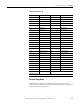
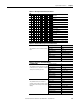
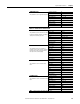
Table 47 - Warning Enable Bit Function Detail
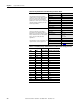
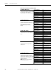
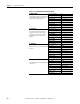
Table 48 - Overload Warning Level Parameter Detail
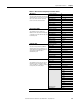
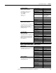
Table 49 - Phase Loss Parameters Detail
Bit
Function15 14 13 12 11 10 9 8 7 6 5 4 3 2 1 0
—
XOverload
—
X Ground Fault (E3 Plus)
—
XJam
X Underload
X PTC (E3 Plus)
X Current Imbalance
X Comm Fault
X Comm Idle
—
—
X PM #Starts — Series C & Later
X PM Oper. Hours — Series C & Later
OL WARN LEVEL
This parameter sets the overload warning
level.
Parameter Number 32
Access Rule Get/Set
Data Type USINT
Object Mapping 2C
hex
-1-132
Group Advanced Setup
Units % Thermal Utilization
Minimum Value 0
Maximum Value 100
Default Value 85
PL INHIBIT TIME
This parameter defines the amount of time
for which phase loss detection is inhibited
during a motor starting sequence.
Parameter Number 33
Access Rule Get/Set
Data Type USINT
Object Mapping 2C
hex
-1-133
Group Advanced Setup
Units Seconds
Minimum Value 0
Maximum Value 250
Default Value 0
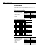
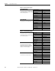
PL TRIP DELAY
This parameter allows the installer to
program a time duration for which a phase
loss condition must exist prior to the device
tripping.
Parameter Number 34
Access Rule Get/Set
Data Type USINT
Object Mapping 2C
hex
-1-134
Group Advanced Setup
Units Seconds
Minimum Value 0.1
Maximum Value 25.0
Default Value 1.0