
Quick Start Manual


Rockwell Automation Publication IASIMP-QS019E-EN-P - August 2013 49
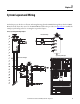
System Layout and Wiring Chapter 3
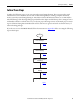
Follow These Steps
Complete the following steps to create your system layout and wiring drawings. These steps provide general
instructions for how to maximize the use of the toolkit’s drawing library in creating a complete drives-and-
motion system layout and wiring drawing set. AutoCAD or AutoCAD Electrical software is recommended to
take full advantage of the drawing editing steps included in this chapter and the library’s device wiring references
and attributes that move with the devices as you edit your project drawing set. Some of the initial project creation
steps are illustrated using AutoCAD Electrical software, but most are generic and can be used with a variety of
software drawing packages.
If you chose not to use the DMAT Wizard, follow the instructions in Appendix F before executing the following
steps in this chapter.
page 50
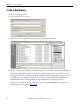
Create a New Project
page 51
Edit Power Drawings
Edit Drive, Controller, and Safety
I/O Drawings
Edit System Communication
Drawings
Edit System Layout Drawings
page 56
page 61
page 62
Start