
Quick Start Manual

Rockwell Automation Publication IASIMP-QS019E-EN-P - August 2013 297
Controller, Network, and Device Configuration Without the DMAT Wizard Appendix G
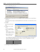
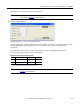
This assigns the associated axes to the control module.
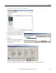
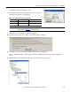
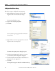
17. Click the Digital Input tab.
The digital inputs (1…4) are assigned default values.
You can reassign them, using the pull-down menus, according to the needs of your application. You can also
unassign digital inputs, if your application does not use them or you want to remove the default
assignments.
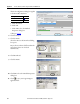
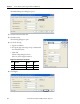
For the Widg-O-matic machine example, digital inputs 1 and 2 are assigned Enable and Home
(respectively) and digital inputs 3 and 4 are unassigned.
IMPORTANT
For PowerFlex 755 CIP Motion drives, you must configure the motor feedback device. Refer to your PowerFlex 755 user
manual, publication 750-UM001
, for more information.
IMPORTANT
PowerFlex 755 CIP Motion drives support only one digital input. Refer to your PowerFlex 755 user manual, publication
750-UM001
, for more information.
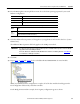
Widg-O-matic X-Y Gantry Digital Input Assignments
Axis Axis Name Digital Input 1 Digital Input 2
1Gantry_X_Axis
Enable
(1)
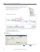
(1) When using the Enable digital input, you can add a check in the device module code to make
sure it is on before running your machine. Refer to the steps below to see how.
Home
2 Gantry_Y_Axis Enable Home