
Quick Start Manual

Rockwell Automation Publication IASIMP-QS019E-EN-P - August 2013 295
Controller, Network, and Device Configuration Without the DMAT Wizard Appendix G
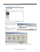
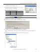
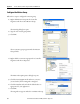
The Module Definition dialog box opens.
8. From the Power Structure pull-down menu, choose the power
module appropriate for your application.
9. Click OK to close the Module Definition dialog box.
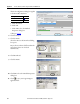
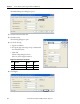
10. Click Yes when prompted to confirm your module definition changes.
11. Click OK to close the New Module dialog box and save the configuration.
The new CIP Motion drive module appears under the EtherNet/IP module in the I/O Configuration
folder.
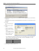
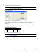
12. Right-click the new CIP Motion module you just created and choose Properties.
IMPORTANT
For PowerFlex 755 CIP Motion drives, you must also choose the motor feedback device. Refer to your PowerFlex 755 user
manual, publication 750-UM001
, for more information.
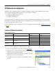
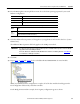
Widg-O-matic X-Y Gantry Power Module Configuration
Module Name Power Module Type Power Structure Cat. No.
Gantry_X_Drive IAM 2094-BC01-M01-M
Gantry_Y_Drive AM 2094-BMP5-M