
Quick Start Manual


Rockwell Automation Publication IASIMP-QS019E-EN-P - August 2013 193
System Application Guide Chapter 7
Faceplate Status/Control Buttons
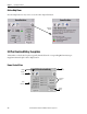
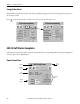
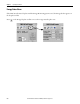
Fault Indication View
The Alarm button indicates a drive fault condition and activates the fault diagnostic views.
Fault Indication View
To access the detailed fault information and action displays, press the alarm button on the toolbar.
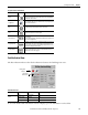
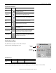
Button Icons Description
Alarm
The Alarm button indicates a fault condition and activates fault diagnostic
views. A grey bell indicates normal status, with no faults. A red flashing
bell indicates a fault condition.
Configuration
The Configuration button lets you edit the E3 Plus overload relay faceplate
name or name of the device.
Help The Help button provides information for the current view.
Close Click the Close button to close the faceplate.
Status Indicators
Grey = OK, normal, off
Red = Tripped
Yellow = Warning/Outputs commanded closed/user device inputs closed
Green = Active load present
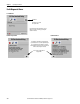
Program/Operator
Toggles the control mode between Program and Operator. Operator mode
permits manual control of the relay from the faceplate. Program mode
operates the relay according to the Logix Designer application. The active
control mode is displayed on the button.
Command Buttons
The command buttons are enabled when in Operator mode. Trip Reset,
Output A, and Output B let the operator perform the E3 Plus overload
relay functions as the names suggest.
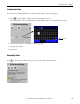
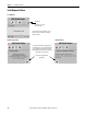
Toolbar Button Color Indicator Description Action
Alarm
Grey Normal state None
Flashing yellow Warning None
Flashing red Fault Follow fault action screen
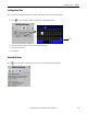
E3 Plus Overload Relay
Flashing Fault
Indicator
Current Fault
Indicator (red)