
Quick Start Manual

Rockwell Automation Publication IASIMP-QS019E-EN-P - August 2013 185
System Application Guide Chapter 7
PowerFlex Drives Faceplates
The PowerFlex drives faceplates are typically launched from the corresponding Machine Startup or Equipment
Status faceplate’s Goto display button.
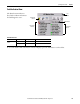
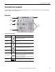
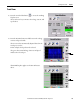
Home View
Faceplate Status/Control Buttons
Button Icons Description
Alarm
(1)
(1) There is no Alarm indication on the PowerFlex 525 drive faceplate because the PowerFlex 525 drive does not support alarms.
The Alarm button indicates a drive fault condition and activates fault
diagnostic views. A grey bell indicates normal status, with no faults. A red
flashing bell indicates a fault condition.
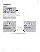
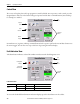
Configuration
The Configuration button lets you edit the PowerFlex faceplate name or
name of the device.
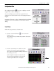
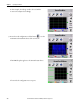
Trending The Trending button shows you voltage, current, and speed trends.
Help The Help button provides information for the existing view.
Close Click the Close button to close the faceplate.
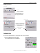
Program/Operator
Toggles the control mode between Program and Operator. Operator mode
permits manual control of the drives from the faceplate. Program mode
operates the drive according to the Logix Designer application. The active
control mode is displayed on the button.
If control mode is switched from Program to Operator while the machine
is RUNNING, the machine is STOPPED.
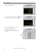
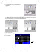
Numeric Display Click the Numeric Display button to access numeric entry keypad.
Faceplate
Toolb ar
Command
Buttons
Status
Indicators
Close
Button
Numeric
Display
Title Bar
PowerFlex Drive