
Quick Start Manual

Rockwell Automation Publication IASIMP-QS019E-EN-P - August 2013 163
System Commissioning Chapter 6
Commissioning Kinetix 300 Drives
These commissioning procedures apply specifically to the Kinetix 300 drives.
For more information on drive commissioning for Kinetix 300 drives, refer to the appropriate user manual listed
in Additional Resources on page 15.
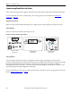
Apply Power to the Drive
If using separate 24V DC logic power, apply 24V DC and observe the four-character display. If the four-character
display is ON, apply mains drive power. If not using separate 24V DC logic power, apply mains drive power.
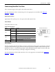
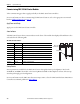
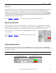
Status Indicators
Verify the drives are ready.
Four-character Display Status Indicators
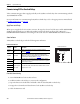
Configure the Drive
Use MotionView OnBoard software to configure the drive/motor combination and the mode required for your
application.
Test and Tune the Drive
Use MotionView OnBoard software to run the Hookup test and Tune test.
• For testing the drive if using an incremental encoder, use MotionView OnBoard software to perform the
Check Phasing test. This test isn’t required if using an absolute encoder.
• For tuning the drive, use MotionView OnBoard software to perform Autotuning. The Auto Tune
procedure calculates the gain values dynamically after determining inertia. To perform Auto Tune, the
drive must be in Auto Tune mode.
For more information on test and tune procedures for Kinetix 300 drives, refer to the appropriate user manual
listed in Additional Resources on page 15.
Status
Indicator
Function Description
A Enable Orange status indicator means that the drive is enabled (running).
B Regen Yellow status indicator means the drive is in Regeneration mode.
C Data entry Yellow status indicator flashes when changing.
D Drive fault Red status indicator illuminates upon a drive fault.
E Comm activity Green status indicator flashes to indicate communication activity.
Kinetix 300 Status Indicators