Quick Start Drives and Motion Accelerator Toolkit
Important User Information Read this document and the documents listed in the additional resources section about installation, configuration, and operation of this equipment before you install, configure, operate, or maintain this product. Users are required to familiarize themselves with installation and wiring instructions in addition to requirements of all applicable codes, laws, and standards.
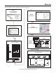
Where to Start Follow this path to complete your Drives and Motion application.
Where to Start Notes: 4 Rockwell Automation Publication IASIMP-QS019E-EN-P - August 2013
Summary of Changes This manual contains new and updated information. New and Updated Information This is a minor revision that reflects changes in the DMAT Wizard. As a result, the Module Definitions example dialog box for PowerFlex® 750-Series datalinks has changed. Refer to page 283 see the new dialog box.
Summary of Changes Notes: 6 Rockwell Automation Publication IASIMP-QS019E-EN-P - August 2013
Table of Contents Preface About this Publication . . . . . . . . . . . . . . . . . . . . . . . . . . . . . . . . . . . . . . . . . . . Conventions. . . . . . . . . . . . . . . . . . . . . . . . . . . . . . . . . . . . . . . . . . . . . . . . . . . . . Required Software . . . . . . . . . . . . . . . . . . . . . . . . . . . . . . . . . . . . . . . . . . . . . . . Studio 5000 Environment . . . . . . . . . . . . . . . . . . . . . . . . . . . . . . . . . . . . . . . . Additional Resources . . . . . . . . . . . .
Table of Contents Edit System Layout Drawings . . . . . . . . . . . . . . . . . . . . . . . . . . . . . . . . . . . . . 62 Chapter 4 Logic Configuration Before You Begin. . . . . . . . . . . . . . . . . . . . . . . . . . . . . . . . . . . . . . . . . . . . . . . . . What You Need. . . . . . . . . . . . . . . . . . . . . . . . . . . . . . . . . . . . . . . . . . . . . . . . . . Follow These Steps . . . . . . . . . . . . . . . . . . . . . . . . . . . . . . . . . . . . . . . . . . . . . . .
Table of Contents Chapter 6 System Commissioning Before You Begin . . . . . . . . . . . . . . . . . . . . . . . . . . . . . . . . . . . . . . . . . . . . . . . What You Need . . . . . . . . . . . . . . . . . . . . . . . . . . . . . . . . . . . . . . . . . . . . . . . . Follow These Steps . . . . . . . . . . . . . . . . . . . . . . . . . . . . . . . . . . . . . . . . . . . . . . Download Applications . . . . . . . . . . . . . . . . . . . . . . . . . . . . . . . . . . . . . . . . .
Table of Contents Trend Views . . . . . . . . . . . . . . . . . . . . . . . . . . . . . . . . . . . . . . . . . . . . . . . . Energy Status Views. . . . . . . . . . . . . . . . . . . . . . . . . . . . . . . . . . . . . . . . . . Online Help Views . . . . . . . . . . . . . . . . . . . . . . . . . . . . . . . . . . . . . . . . . . E3 Plus Overload Relay Faceplates . . . . . . . . . . . . . . . . . . . . . . . . . . . . . . . . Home/Control View . . . . . . . . . . . . . . . . . . . . . . . . . . . . . . . .
Table of Contents Appendix D Logix Designer Communication and Controller Configuration Configure Personal Computer Communication Properties . . . . . . . . . 235 Configure the EtherNet/IP Driver . . . . . . . . . . . . . . . . . . . . . . . . . . . . . . . 237 Configure the Logix5000 Controller . . . . . . . . . . . . . . . . . . . . . . . . . . . . . 238 Appendix E Create and Add BOM Device Modules Before You Begin . . . . . . . . . . . . . . . . . . . . . . . . . . . . . . . . . . . . . . . . . . . . .
Table of Contents Sercos Motion Drive Configuration. . . . . . . . . . . . . . . . . . . . . . . . . . . . . . . Configure Sercos Drive Modules . . . . . . . . . . . . . . . . . . . . . . . . . . . . . . Configure the Motion Group. . . . . . . . . . . . . . . . . . . . . . . . . . . . . . . . . Configure Axis Properties . . . . . . . . . . . . . . . . . . . . . . . . . . . . . . . . . . . . Kinetix 300 Drive Configuration . . . . . . . . . . . . . . . . . . . . . . . . . . . . . . . . .
Preface About this Publication This quick start provides step by step instructions for using the Drives and Motion Accelerator Toolkit to help you design, install, operate, and maintain a drive system. Included are selection tools, layout and wiring drawings, and pre-configured logic and HMI files to assist you in creating an Integrated Architecture™ solution for your application requirements.
Preface Conventions Convention Meaning Example CIP Motion Used as an abbreviation for Integrated Motion on the EtherNet/IP network. This term describes Rockwell Automation servo drives and high-power AC drives that use CIP Motion and CIP Sync technology from ODVA, all built on the Common Industrial Protocol (CIP) communicating over the EtherNet/IP network. Two drive platforms that apply are Kinetix® 6500 servo drives and PowerFlex 755 AC drives when used on the EtherNet/IP network.
Preface Studio 5000 Environment The Studio 5000 Engineering and Design Environment combines engineering and design elements into a common environment. The first element in the Studio 5000 environment is the Logix Designer application. The Logix Designer application is the rebranding of RSLogix 5000 software and will continue to be the product to program Logix5000™ controllers for discrete, process, batch, motion, safety, and drive-based solutions.
Preface Resource Description PowerFlex 70 EtherNet/IP Adapter User Manual, publication 20COMM-UM010 PowerFlex 70 DeviceNet Adapter User Manual, publication 20COMM-UM002 Provides details on how to install, configure, and use the adapter.
Chapter 1 Initial System Configuration Using the DMAT Wizard In this chapter you use the Drives and Motion Accelerator Toolkit (DMAT) Wizard to create an initial bill of materials, assemble a system drawing set, and create a Studio 5000 Logix Designer project file with a preconfigured controller, network, drives and initial system program logic.
Chapter 1 Initial System Configuration Using the DMAT Wizard Before You Begin Collect specific application data, for example: • System Input Voltage • Ambient temperature and Altitude Specifications • Transmission Type • Motor data • Load Data – Inertia and Cycle Profiles • Other System Sizing Info What You Need • The Drives and Motion Accelerator Toolkit DVD, publication IASIMP-SP017. For a copy of the DVD, contact your local Rockwell Automation distributor or sales representative.
Initial System Configuration Using the DMAT Wizard Chapter 1 Review the DMAT Wizard Once you have a general idea of the overall control architecture, relative size, and type of the drives in your system, you can use the DMAT Wizard to create a bill of material, assemble a system drawing set, and create a Logix Designer application project file with a preconfigured controller, network, drives, and initial system program logic.
Chapter 1 Initial System Configuration Using the DMAT Wizard System Drawing Set Output The assembled system drawing set includes power distribution, drive power and control wiring, communication, and system layout drawings in .dwg, .dxf, or .pdf formats. Drive I/O Example System Layout Example Drive Power Example AC Line Filter LIM Module Insert images diagonal/down/partial overlap ,
Initial System Configuration Using the DMAT Wizard Chapter 1 Project File Output The project file includes preconfigured controller, drives, network, and machine/application/ device program logic providing an integrated logic architecture to add your specific application logic to. The preconfigured file saves hours in logic configuration and assembly. MODULE COMMANDS NOP 3 RESET Machine Commands Mach_Ctrl.Cmd.RESET 4 ONS[0].5 ONS Servo Ready for Use Servo_Ctrl.Status.
Chapter 1 Initial System Configuration Using the DMAT Wizard FactoryTalk View Me Project File Output The FactoryTalk View Me ConfigurationGuide folder contains two files. The FactoryTalk View Me (.apa) file contains the basic screens and parameters needed for a DMAT Wizard application. The folder also includes a Word document with custom instructions on how to adopt the example file to your application drive set and prepare it to add any additional screens.
Initial System Configuration Using the DMAT Wizard Chapter 1 Review Other System Selection and Configuration Tools Rockwell Automation provides a variety of other system selection and configuration tools. Motion Analyzer Software Motion Analyzer software is a comprehensive standard-drives and motion-control application sizing tool used for analysis, optimization, selection, and validation.
Chapter 1 Initial System Configuration Using the DMAT Wizard Profile Data Solution Options Engineering Assistant Software Engineering Assistant software provides inertia, power/ torque, braking, and other application specific calculators and formulas to assist you in sizing the motor, drive, and transmission for your application. Use this software as a supplement to Motion Analyzer.
Initial System Configuration Using the DMAT Wizard Chapter 1 Product Selection Toolbox Product Selection & System Design Tools The Rockwell Automation Product Selection Toolbox (PST) offers a complete suite of user tools for product selection and configuration across product lines from project conception through final design.
Chapter 1 Initial System Configuration Using the DMAT Wizard Install Other System Selection and Configuration Tools You can install the system selection and configuration software tools from the Drives and Motion Accelerator Toolkit DVD or download them from the Web. Install Motion Analyzer Software 1. Navigate to and select the Motion Analyzer Installation application on the toolkit DVD. The Motion Analyzer Welcome dialog box opens. 2. Click Next and follow installation instructions.
Initial System Configuration Using the DMAT Wizard Chapter 1 Install Product Selection Toolbox Follow these steps to install desired tools from the Product Selection Toolbox. ProposalWorks software installation is the minimum requirement for completing your system bill of materials in the next chapter. 1. Navigate to and select the System Selection and Configuration Tools Installation application on the Drives and Motion Accelerator Toolkit DVD.
Chapter 1 Initial System Configuration Using the DMAT Wizard Run the DMAT Wizard The DMAT Wizard creates an initial bill of materials, assembles a system drawing set, and creates a Logix Designer project file with preconfigured controller, network, drives, and initial system program logic. All this in just minutes by executing the following steps. If you prefer to build these initial files using the traditional application tools, skip over this section and go directly to Chapter 2.
Initial System Configuration Using the DMAT Wizard Chapter 1 The Open or Create a Project dialog box opens. 3. Click Create New to initiate a new project. Another configuration information dialog appears explaining machine, application, and drive configuration. 4. Read configuration information dialog box and click OK to continue. 5. The New Project Wizard dialog box opens. a. Enter Project Name. b. Enter Project Description (optional). c. Click Next. 6.
Chapter 1 Initial System Configuration Using the DMAT Wizard 12. Click the Application_x edit fields and rename the application names. For the Widg-O-matic example, the two applications were renamed Assembly and Packaging. 13. From the Low-Voltage drives pull-down menus, choose the number of low-voltage drives to assign to each application. For the Widg-O-matic example, the quantity was set to 0 for the Assembly application and 1 for the Packaging application. 14.
Initial System Configuration Using the DMAT Wizard Chapter 1 Edit the DMAT Wizard Configuration Follow these steps to continue editing the DMAT Wizard configuration. 1. Edit your Machine Configuration. a. Click the machine in your project configuration tree. In this example, the machine name is WidgOmatic. The Machine editing window appears to the right of the project tree. b. Click the Machine Name edit field to change the machine name. c.
Chapter 1 Initial System Configuration Using the DMAT Wizard 3. Edit the SERCOS, CIP Motion, and Ethernet/IP Indexing Servo Drive Configurations. a. Select a servo drive in the project configuration tree. For the WidgOmatic example, CIP_Motion_Servo_Drive_1 was selected. The drive editing window appears to the right of the project configuration tree. b. Click the Drive Name edit field and enter the desired drive name. For the WidgOmatic example, Gantry_X was entered as the initial drive name. c.
Initial System Configuration Using the DMAT Wizard Chapter 1 4. For multi-axis servo drive types, select an integrated axis module (IAM) for the first drive of its type. For the WidgOmatic example, the Gantry_X drive is configured as an IAM module. a. From the Spare Slot Count pull-down menu, choose the number of spare slots available on the Bulletin 2094 power rail. b. From the Inverter Current Rating pull-down menu, choose the inverter current rating for your drive. c.
Chapter 1 Initial System Configuration Using the DMAT Wizard 5. For single-axis drive types or secondary multi-axis servo drives, select the appropriate axis module (AM) configuration option. For the WidgOmatic example, the Gantry_Y drive is a Kinetix 6500 (K6500) AM module. a. From the Inverter Current Rating pull-down menu, choose the inverter current rating for your drive. b.
Initial System Configuration Using the DMAT Wizard Chapter 1 6. Edit the Low-Voltage Drive configurations. a. Select Low_Voltage_Drive_x in the project configuration tree. For the WidgOmatic example, Low_Voltage_Drive_1 was selected. The drive editing window appears to the right of the project configuration tree. b. Click the Drive Name edit field and enter the desired drive name. For the WidgOmatic example, Conveyor_Drive was entered as the initial drive name. c.
Chapter 1 Initial System Configuration Using the DMAT Wizard 8. Generate the Output Files. Before you can generate a DMAT file, all red highlighted items must be cleared in your configuration. a. Click Generate on the DMAT Wizard toolbar. The Generate Outputs dialog box opens. b. Check the Drawing Types you wish to have generated as part of the output files. c. Click Generate. The DMAT Wizard generates a folder containing the output files.
Chapter 2 Bill of Materials Completion In this chapter you use Rockwell Automation ProposalWorks software to complete the drives and motion system bill of materials that the DMAT Wizard created. If you chose not to use the DMAT Wizard, follow the procedures in Appendix E to assemble the initial BOM ProposalWorks file before executing the following steps in this chapter.
Chapter 2 Bill of Materials Completion Follow These Steps Complete these steps to complete the commissioning process for your drives and motion application. Start Import the Initial Project BOM File page 38 Edit Your Project BOM File page 40 Import the Initial Project BOM File Follow these steps to import the initial project BOM file. 1. Open ProposalWorks software, navigate to File Menu>Utilities, and select Import.
Bill of Materials Completion Chapter 2 2. Navigate to your projects .bom file and click Open. If the default DMAT Wizard directory was used, your project's .bom import file is in C:\Documents and Settings\PC Name\My Documents\DMAT\ProjectName\MachineName\BOM directory. The Widg-O-matic example file may be found in: C:\Program Files\RA_Simplification\DMAT\B-Files\ 6-Project Examples\Widg-O-matic. The ProposalWorks file opens. 3. Click Refresh to update prices in local currency.
Chapter 2 Bill of Materials Completion Edit Your Project BOM File The DMAT Wizard you used in Chapter 1 or the steps you followed in Appendix E created an initial bill of materials (BOM), however, individual preconfigured product listings should be reviewed and possibly edited to fit your specific application needs. ProposalWorks software includes a variety of specific product configuration tools to make further BOM adjustments easy.
Bill of Materials Completion Chapter 2 b. Click the Current Rating attribute. In this example, the Current Rating option is 25 A. For more in-depth product selection information, refer to product selection guides or Motion Analyzer software.
Chapter 2 Bill of Materials Completion c. For this example, select 15 A under the Current Rating field. The catalog number field is replaced with 1489-A2D150. d. Click Accept to make the product change within the Product Configuration Assistant. The Product Configuration Assistant closes and your BOM file reflects the change.
Bill of Materials Completion Chapter 2 2. Edit a product group for your specific application. Product group refers to an item (catalog number) that includes one or more sub items. a. Double-click a product group catalog number to activate the Product Configuration Assistant. In this example, item 13 (catalog number 2094-BMP5-M) with sub items 13.1 and 13.2 was selected. The Product Configuration Assistant dialog box opens. You can browse and select from a variety of product options. b.
Chapter 2 Bill of Materials Completion c. For this example, select 15 A under the Inverter Current Rating field. The catalog number field was replaced with 2094-BM02-M. In addition, the 2094-EN02D-M01-S1 control module was chosen to replace the 2094-EN02D-M01-S0. d. Click Accept to make the product change within the Product Configuration Assistant. Sub item (13.2) also reflects the updated catalog number and description.
Bill of Materials Completion Chapter 2 3. Delete products not required for your specific application. a. Select the product or product group not required for your application. In this example, items 37 and 38 were selected. b. From your keyboard, press delete. The product or products are deleted from the BOM project file. 4. Save your edited BOM project file. 5. Send the BOM project file to your Rockwell Automation distributor for a quote.
Chapter 2 Bill of Materials Completion Notes: 46 Rockwell Automation Publication IASIMP-QS019E-EN-P - August 2013
Chapter 3 System Layout and Wiring In this chapter you edit the set of layout and wiring drawings from the DMAT drawing library that the DMAT Wizard created. If you chose not to use the DMAT Wizard, follow the procedures in Appendix F to assemble the initial project drawing set before executing the steps in this chapter.
Chapter 3 System Layout and Wiring To assist you in understanding how to best use the drawing libraries, the Widg-O-matic machine application example is used in the drawing editing steps provided.
System Layout and Wiring Chapter 3 Follow These Steps Complete the following steps to create your system layout and wiring drawings. These steps provide general instructions for how to maximize the use of the toolkit’s drawing library in creating a complete drives-andmotion system layout and wiring drawing set.
Chapter 3 System Layout and Wiring Create a New Project 1. Open your drawing software. 2. Create and name your new project. 3. Add and select the toolkit library drawings assembled by the DMAT Wizard. 4. Navigate to the appropriate DWG or DXF Drawing directory that was created by the DMAT Wizard. If the default DMAT Wizard directory was used, your project's drawing set is in C:\Documents and Settings\PC Name\My Documents\DMAT\ProjectName\MachineName\Drawings\filetype directory.
System Layout and Wiring Chapter 3 Edit Power Drawings 1. Open your initial drive power drawing that includes the main power distribution components. For the Widg-O-matic machine application example, the 010_K6500_460VAC_w_LIM.dwg file is opened. Refer to the figure on page 52. 2. Delete drives not used in your project. For the Widg-O-matic machine application example, only two Kinetix 6500 drives are required, so the third drive is deleted. Refer to the shaded area in the figure on page 52. 3.
Chapter 3 System Layout and Wiring Select and delete this drive.
System Layout and Wiring Chapter 3 Select and delete this drive. Select and delete this drive. Select and delete this drive.
Chapter 3 System Layout and Wiring Select and delete this drive. Select and delete this drive. Select and delete this drive.
System Layout and Wiring Chapter 3 ControlLogix/GuardLogix® (120V) Control Power with LIM Module Rockwell Automation Publication IASIMP-QS019E-EN-P - August 2013 55
Chapter 3 System Layout and Wiring Edit Drive, Controller, and Safety I/O Drawings 1. Open all drive, controller, and safety I/O drawings as required for your application. For the Widg-O-matic machine application example, the 060_K6500_Digital_IO.dwg file is opened. 2. Delete devices not used in your project. For the Widg-O-matic machine application example, only two Kinetix 6500 drives are required, so the third and fourth I/O blocks are deleted.
System Layout and Wiring Chapter 3 3. Add standard or unique I/O devices and connections required for your application. For the Widg-O-matic machine application example, the Enable on-off switches and Home proximity switches are added to both Kinetix 6500 drives (input 1 and 2 respectively). Kinetix 6500 Drives (add digital I/O devices) 4. Repeat step 1…step 3 for all I/O drawings within your project.
Chapter 3 System Layout and Wiring Additional I/O library drawings, used for the Widg-O-matic machine example, are available from the Drives and Motion Accelerator toolkit DVD. These drawings represent a sample of drive and controller I/O drawings. Additional I/O Library Drawing Examples I/O Library Drawings File Name Page Kinetix 6500 Drive Safety I/O 070_K6500_Safety_IO.dwg 58 Kinetix 6500 Drive Feedback 080_K6500_Feedback.dwg 59 ControlLogix Controller Digital Inputs 090_CLX_Digital_Inputs.
System Layout and Wiring Chapter 3 Kinetix 6500 Feedback Rockwell Automation Publication IASIMP-QS019E-EN-P - August 2013 59
Chapter 3 System Layout and Wiring ControlLogix Digital Inputs 60 Rockwell Automation Publication IASIMP-QS019E-EN-P - August 2013
System Layout and Wiring Chapter 3 Edit System Communication Drawings 1. Open the communication drawing for your application. For the Widg-O-matic machine application example, the 060_120_Ethernet_Communication.dwg file is opened. 2. Delete network devices not used in the project. For the Widg-O-matic machine application example, one of the Kinetix 300 drives and associated cable is deleted. Ethernet Communication Select and delete this drive and cable.
Chapter 3 System Layout and Wiring 3. Add any network device footprints required for your application. a. Navigate to and open the required footprint drawings that were added to your Project Drawings folder from the toolkit library. b. Copy device footprints from the footprint drawings. In this example, Kinetix 6500 IAM and AM module footprints are copied.
System Layout and Wiring Chapter 3 Small Panel Layout Drawing (power distribution) AC Line Filter LIM Module Power Distribution Section C2 CLEAN CLEAN wireway for noise sensitive device circuits. DIRTY D6 DIRTY wireway for noise generating device circuits.
Chapter 3 System Layout and Wiring 2. Replace or add power components to your panel layout drawing. a. Inspect power section on layout drawing for proper component footprints for the project. b. Open the associated power footprint drawings that were added to your project drawings from the toolkit library. In this example, the 510_Line_Filter_Footprints.dwg file is opened. Line Filter Footprint Drawing Examples FP_2090-UXLF-136 FP_2090-UXLF-HV330 FP_2090-XXLF-X330B FP_2090-XXLF-375B_3d c.
System Layout and Wiring Chapter 3 3. Insert drives into the Drives Placement section. a. Open the panel layout drawing for your application. Small Panel Layout Drawing AC Line Filter LIM Module Drives Section C2 CLEAN CLEAN wireway for noise sensitive device circuits. DIRTY D6 DIRTY wireway for noise generating device circuits. b. Open the associated drives footprint drawings that were added to your project drawings from the toolkit library.
Chapter 3 System Layout and Wiring Kinetix 6200/6500 Drive Footprint Drawings FP_2094-B_6500 FP_2094-B_6500 FP_2094-B_6500 FP_2094-BM_6500 FP_2094-BM_6500 FP_2094-BM_6500 Copy this Kinetix 6500 AM module. Copy this Kinetix 6500 IAM module. d. Paste the drive footprints onto the panel layout drawing. For the Widg-O-matic machine application example, two Kinetix 6500 servo drives, one PowerFlex 753 drive, and one Kinetix 300 drive was added to the layout drawing.
System Layout and Wiring Chapter 3 4. Inspect control section for required control components and proper footprints. a. Open the panel layout drawing for your application. Small Panel Layout Drawing (control) AC Line Filter LIM Module C2 CLEAN CLEAN wireway for noise sensitive device circuits. DIRTY Controller and I/O Section D6 DIRTY wireway for noise generating device circuits. b.
Chapter 3 System Layout and Wiring 5. Edit your Enclosure Layout Drawing. a. Open the enclosure layout drawing for your application. For the Widg-O-matic machine application example, the 140_SM_Enclosure_Layout.dwg file is opened. Small Enclosure Layout Drawing b. Inspect the drawing for operator equipment required for your system. c. Open the associated enclosure footprint drawings that were added to your project drawings from the toolkit library.
System Layout and Wiring Chapter 3 PanelView Plus Footprint Drawings FP_2711P-B6C20A_FRONT FP_2711P-B10C FP_2711P-B15C FP_2711P-T7C FP_2711P-T10C FP_2711P-T15C FP_2711P-T6C d. Copy the desired enclosure components from the footprint drawings for your enclosure layout drawing. e. Paste the enclosure component footprints onto your panel layout drawing. f. Add any other required enclosure components for your system.
Chapter 3 System Layout and Wiring Notes: 70 Rockwell Automation Publication IASIMP-QS019E-EN-P - August 2013
Chapter 4 Logic Configuration In this chapter you edit the preconfigured logic file that the DMAT Wizard created for your specific application. Besides initial controller, network, and device configurations, the preconfigured logic file includes machine, application, and device logic modules that significantly speed-up your application logic development.
Chapter 4 Logic Configuration The application modules execute the machine commands and provide the more specific application commands to the drives and devices. It also coordinates the machine and application status, and executes the application fault commands. In addition, the toolkit includes motion logic examples to help you create your specific application logic.
Logic Configuration Chapter 4 Follow These Steps Complete these steps to import and configure logic modules for your drives and motion application. Import the Preconfigured Logix Designer Project Start page 74 Complete Drive and Motor Configuration page 76 Set String Tag Names for Alarm History Faceplate Optional Step Complete if Alarm History faceplate is used in application.
Chapter 4 Logic Configuration Import the Preconfigured Logix Designer Project Follow these steps to open the preconfigured RSLogix 5000 or Studio 5000 Logix Designer project. This procedure is written for the Logix Designer application, but RSLogix 5000 software is similar. 1. From the Start menu, launch the Studio 5000 Logix Designer application. The Studio 5000 dialog box opens. 2. Under the Create menu, click From Import. 3. Navigate to the Logic directory within the DMAT project.
Logic Configuration Chapter 4 For the Widg-O-matic example, the path is: C:\Program Files\RA_Simplification\DMAT\D-Wizard\WidgOmatic\WidgOmatic\Logic. 4. Select the logic xml file and Click Open. 5. From the Revision pull-down menu, choose the version of RSLogix 5000 software, versions 18, 19, or 20, or the Logix Designer application, version 21 or later, to import into. IMPORTANT RSLogix 5000 software must be version 19.0 or later. RSLogix 5000 software, version 20.
Chapter 4 Logic Configuration Complete Drive and Motor Configuration The DMAT Wizard uses default values for module properties (creating your axes) and axis properties (configuring your axes). When your application requires modifications to these fields, refer to the appropriate steps in Appendix G. Changing Default Properties in Appendix G Procedure Go To Do This Complete CIP motion drive module configuration step 19 on page 298 Calculate and enter a value for the Bus Capacitance field.
Logic Configuration Chapter 4 Set String Tag Names for Alarm History Faceplate If you plan to use the Alarm History faceplate with your HMI application, follow these steps to set the application and device string tag names to match your application and device module names. These string names are used within the alarm messages indicating the device or application origin of the alarm. 1. Expand the Controller folder in your Controller Organizer and double-click Controller Tags.
Chapter 4 Logic Configuration For the Widg-O-matic application example, these application and device string tag names were entered.
Logic Configuration Chapter 4 Set Visible Rows for Equipment Status Faceplate If you plan to use the Equipment Status faceplate with your HMI application, follow these steps to set the Inp_NumRowsVis tag value within the faceplate AOI of the device you intend to place in the first row. 1. Determine how many of the nine available rows you will use in the Equipment Status faceplate.
Chapter 4 Logic Configuration Set Visible Rows for Equipment Status Faceplate for Energy Monitoring If you plan to use the Equipment Status faceplate with Energy Monitoring in your HMI application, follow these steps to set the Inp_NumRowsVis tag value within the energy object AOI of the device you intend to place in the first row. 1. Determine how many of the nine available rows you will use in the Equipment Status faceplate for Energy.
Logic Configuration Chapter 4 Set MSG Path in the E3 Plus Energy Monitoring Routine If the device modules with energy monitoring are used, an additional routine is included in the device program named R05_Energy. This routine gathers the energy data and energy related status and stores the data in the base energy object tag (UDT_BEO). Rung 2 of the energy routine includes at least one explicit message for getting energy attributes from the device (some devices require more than one explicit message).
Chapter 4 Logic Configuration Create Specific Application Logic Now that you have imported and configured all of the machine, application, and device modules, you can begin creating the specific application logic for your machine. You create your application logic within the R10_ApplicationCode routine of the application module. There are two methods for creating specific application logic for your machine.
Logic Configuration Chapter 4 Run Sequence Template ============================================ BY DEFAULT THE FOLLOWING RUNGS WILL BE ERRORED AND THEREFORE MUST BE ADDRESSED...
Chapter 4 Logic Configuration The run sequence is initiated by a machine START command via the start logic in the R03_Control routine of the application module. By default, the run sequence is initiated by placing a value of 1 in the RunSEQ[0] tag. When the RunSEQ[0] tag is set to 1, the first step in the run sequence is executed, starting the run sequence. Each of the rungs in the run sequence provides a placeholder where you can insert application-specific step logic.
Logic Configuration Chapter 4 Final Run Sequential Step Example Much like the first run-step example rung, this Widg-O-matic final run step example also includes a motion axis move (MAM) instruction, an instruction error detection check, and an process complete (PC) check. The only difference is that the PC bit is used to reset the RunSEQ[0] tag back to a value of 1, which will repeat the motion sequential steps for continuous operation.
Chapter 4 Logic Configuration Stop Sequence Template ============================================ STOP SEQUENCE ============================================ 5 6 7 8 NOP e e e e e e e e e e e e e e e e e e e e e e e e e e e e e e e SEQUENCE INITIATE This rung is a placeholder where Application specific logic can be inserted. By default, StopSEQ[0] is initially set to 1 following a Machine STOP command (i.e. "MachineName".Cmd.STOP).
Logic Configuration Chapter 4 The move (MOV) instruction is a placeholder to advance the stop sequence to the next step by incrementing the StopSEQ[0] tag. Each step in the stop sequence requires a unique value be assigned in ascending order. The steps typically increase by multiples of five or ten. By default, the stop sequence-template steps 1…10…20…30 …999. Before moving to the next step, a predetermined condition must normally be met to make sure the current step is complete.
Chapter 4 Logic Configuration Final Stop Sequential Step and Sequence Complete Example This Widg-O-matic final-stop step and complete logic example includes logic to disable the two axes and confirm that the axes are disabled before confirming the application is stopped. Identical to the stop-sequence template, the stop-sequence complete rung sets the StopSEQ[0] tag value to 999 which indicates the stop sequence is complete.
Logic Configuration Chapter 4 Kinetix 300 Logic Examples Application Example File Name Description EIP Position K300_EIPMove_App Enter position, speed, and accel/decel rates to perform incremental position moves. EIP Velocity K300_EIPVel_App Run Kinetix 300 drive at a speed reference. Index K300_Index_App Configure and run Kinetix 300 drive in indexing mode. Application Example File Name Description 2-Axis Gear Motion_Gear_App Gear two axes together.
Chapter 4 Logic Configuration Widg-O-matic Logic Example Overview To assist you in understanding how to best use the logic examples, the Widg-O-matic machine application is used as an example. We recommend you study the Widg-O-matic assembly and packaging applications to see the interaction of the machine, application, and device modules within the application logic. The Widg-O-matic examples are created by using basic drives and motion application examples included in the toolkit.
Logic Configuration Chapter 4 The Widg-O-matic machine example has two applications (assembly and packaging) and has the following run sequences. Assembly Application Step Simple X-Y Gantry Run Sequence Value 1 Lower Y-axis, incremental distance 2.0 revs 2 Dwell, time 1.0 s 3 Raise Y-axis, incremental distance 2.0 revs 4 Extend X-axis, incremental distance 3.0 revs 5 Lower Y-axis, incremental distance 2.0 revs 6 Dwell, time 1.0 s 7 Raise Y-axis, incremental distance 2.
Chapter 4 Logic Configuration Import Application Logic Examples Follow these steps to add logic examples to your R10_ApplicationCode routine within your application modules. 1. Expand the Tasks folder in the Controller Organizer. 2. Navigate to and open the R10_ApplicationCode routine within your first application program file. For the Widg-O-matic application example, the R10_ApplicationCode routine within the P02_Assembly program was opened. 3. Select all rungs of the R10_ ApplicationCode routine. 4.
Logic Configuration Chapter 4 5. Navigate to the 02_Application Logic folder within the toolkit’s files folder. Your personal computer’s harddrive path is C:\Program Files\RA_Simplification\DMAT\B-Files\02_Application Logic. 6. Double-click the logic examples folder of choice. For the Widg-O-matic application example, the Widg-O-matic_Logic_Examples folder was opened. 7. Select the desired logic example file to start your application logic. For the Widg-O-matic application example, the WOm_Assy_App1.
Chapter 4 Logic Configuration The Import Configuration dialog box opens. 10. Click Tags within the Import Content organizer. The Configure Tag References dialog box opens. 11. Replace tag names in the Final Name column with the associated axis or drive names for your application. For the Widg-O-matic application example, _X_AxisName was replaced with Gantry_X_Axis and _Y_AxisName was replaced with Gantry_Y_Axis. 12. Click OK to complete rung import. 13.
Logic Configuration Chapter 4 For the Widg-O-matic Assembly application example, the following rungs are imported. The rungs include a series of five incremental moves.
Chapter 4 Logic Configuration For the Widg-O-matic application example, the R10_ApplicationCode routine within the P03_Packaging program was also opened and the WOm_Pack_App2.L5X file was imported.
Logic Configuration Chapter 4 For the Widg-O-matic WOm_Pack_App2.L5X file import, the PowerFlex 753 faceplate _Conveyor_DriveName is replaced with Conveyor_Drive and the Kinetix 300 input, output, and control tag _Diverter_DriveName are replaced with Diverter_Drive. IMPORTANT For application examples with Kinetix 300 devices, it is required that you also configure the component reference tag name for the Kinetix 300 drive.
Chapter 4 Logic Configuration For the Widg-O-matic packaging example, the following rungs are imported. The rungs include a series of incremental moves for the Kinetix 300 Diverter_Drive and Start/Stop and Speed reference commands for the PowerFlex Conveyor_Drive.
Logic Configuration Chapter 4 Application Logic Creation Steps Using Template If you are familiar with Rockwell Automation’s general Logix5000 commands, Logix5000 motion commands, PowerFlex parameters, and have a good idea of your specific run/stop sequences, use these steps to guide you through your specific application logic creation. 1. Formulate and list your run sequence steps. 2.
Chapter 4 Logic Configuration Notes: 100 Rockwell Automation Publication IASIMP-QS019E-EN-P - August 2013
Chapter 5 FactoryTalk View ME Configuration In this chapter you create the operator interface application file for your system using FactoryTalk View Studio software. The toolkit includes a variety of preconfigured machine and device faceplate displays providing status, control, and diagnostics for your drives and motion system. Like the logic modules, the faceplates are designed to be used independently of each other or assembled together based on your specific application requirements.
Chapter 5 FactoryTalk View ME Configuration Device Faceplate Display Example • The device faceplates are complex displays providing status, control, and fault diagnostic views for a specific device. • The toolkit includes device faceplates for CIP Motion, Sercos interface, PowerFlex, Kinetix 300, SMC-50, and E3 Plus overload relay (with 193-DNENCAT) devices. • This example shows specific views for the CIP Motion faceplate, other devices are similar, however, differences do exist.
FactoryTalk View ME Configuration Chapter 5 Alarm History Faceplate Display The Alarm History display provides time and date stamped machine and device faults and alarms. This display is sized for use in PanelView Plus 700 or larger terminals. Equipment Status Faceplate Display This Equipment Status display provides a summary status of the devices in your system and a launch site for your individual device faceplate displays. This display is sized for use in PanelView Plus 700 or larger terminals.
Chapter 5 FactoryTalk View ME Configuration Follow These Steps This chapter provides two HMI application configuration options: • Designing from a preconfigured HMI application file • Designing from an existing HMI application file Complete these steps to create your Logix5000 controller logic for your drives and motion application.
FactoryTalk View ME Configuration Chapter 5 Open FactoryTalk View ME Configuration Guide If the DMAT Wizard was used to create the initial system configuration, then there is a corresponding FactoryTalk View ME Configuration Guide for your project to assist you in designing your FactoryTalk View ME application. 1. Navigate to your project's FactoryTalk View ME Configuration Guide.
Chapter 5 FactoryTalk View ME Configuration Restore and Open a Preconfigured HMI Application Follow these steps to restore the preconfigured HMI file and open in FactoryTalk View Studio software. 1. Navigate to the HMI application files within the toolkit’s file folder and open either the PanelView Plus 1000 or PanelView Plus 600 folder, based on the terminal size and faceplate requirements of your application.
FactoryTalk View ME Configuration Chapter 5 The Application Manager dialog box opens. 3. Verify the application archive to restore and that Restore the FactoryTalk View Machine Edition application is selected. IMPORTANT Selecting Restore the FactoryTalk View Machine Edition application and FactoryTalk Local Directory causes the local security settings on your personal computer to substitute for the security setting from the preconfigured application. 4. Click Next. 5.
Chapter 5 FactoryTalk View ME Configuration The New/Open Machine Edition Application dialog box opens. 8. From the Existing tab, select the application file that you just restored. For the Widg-O-matic machine application example, Widg_O_Matic is selected. 9. Click Open. The application opens in FactoryTalk View Studio software.
FactoryTalk View ME Configuration Chapter 5 Delete Unused Displays Follow these steps to remove displays not used in your application. 1. Determine the required faceplates for your application based on the Faceplate Displays table. TIP Only one faceplate display is required for devices/modules of the same type.
Chapter 5 FactoryTalk View ME Configuration For the Widg-O-matic example, these displays are used: Widg-O-matic Application Example Display Names PVP1000_AlarmHistory_Faceplate PVP1000_EquipmentStatus_Faceplate PVP1000_Startup_Faceplate PVP1000_StateDiagram_Faceplate CIPMotion_Faceplate K300_Faceplate PowerFlex_753_755_Faceplate 2. Expand the Displays component under the Graphics folder. 3. Right-click displays not needed in your application and choose Delete. 4.
FactoryTalk View ME Configuration Chapter 5 Configure Parameter Files Follow these steps to configure a parameter file for each device or logic module in your application supported by a faceplate. 1. Right-click a parameter file for a device in your application and choose Rename. 2. Rename the parameter file with the name of the corresponding device in your Logix Designer application. If more than one device uses the same faceplate then another parameter of the same type must be duplicated and renamed.
Chapter 5 FactoryTalk View ME Configuration 4. To create another parameter file based on an existing one, right-click the parameter file and choose Duplicate. For the Widg-O-matic machine application example, Gantry_X_Axis and Gantry_Y_Axis use the same CIP_Motion_Faceplate, but require individual parameter files. For example, Gantry_X_Axis is duplicated and renamed to Gantry_Y_Axis in step 5. 5. Rename the parameter file as needed for your application. 6. Click OK. 7.
FactoryTalk View ME Configuration Chapter 5 The Widg-O-matic Gantry_X_Axis parameter #2 is assigned to the faceplate AOI tag named Gantry_X_Axis_FP found in the R02_Monitor routine of the P04_Gantry_X_Drive program. a. Double-click the parameter file to open it. b. Enter your application controller’s shortcut name in all parameters. TIP Less editing is required when assigning HMI alarm tags if you name your controller shortcut [CLX].
Chapter 5 FactoryTalk View ME Configuration For the Widg-O-Matic example, the parameters are edited as follows: Widg-O-Matic Parameter File Gantry_X_Axis Gantry_Y_Axis Conveyor_Drive Diverter_Drive Parameter File Configuration #1=::[CLX] #2=::[CLX]Gantry_X_Axis_FP #1=::[CLX] #2=::[CLX]Gantry_Y_Axis_FP #1=::[CLX]Conveyor_Drive_FP #1=::[CLX] #2=::[CLX]Diverter_Drive_FP #1=::[CLX]Gantry_X_Axis_FP #2=::[CLX]Gantry_Y_Axis_FP #3=::[CLX]Conveyor_Drive_FP #4=::[CLX]Diverter_Drive_FP EquipmentStatus #5=::[CLX]
FactoryTalk View ME Configuration Chapter 5 Delete Unused Alarm Triggers and Tags Follow these steps to delete any alarm triggers for hardware devices not used in your application. This could improve performance of your PanelView Plus terminal communication. IMPORTANT These steps must be completed if a machine module is not used in your Logix Designer project. 1. Expand the Alarms folder. 2. Double-click Alarm Setup. The Alarm Setup dialog box opens. 3. Click the Triggers tab. 4.
Chapter 5 FactoryTalk View ME Configuration 8. Expand the HMI Tags folder and double-click Tags. The HMI Tags editor appears in the workspace. 9. Select each of the xxxAlarmHandshake, xxxAlarmName, and xxxAlarmTrigger tags associated with each of the Alarm Triggers that were deleted in the previous steps. For example, the circled tags are the three tags you would delete if the E3AlarmTrigger had been deleted previously. 10. Click to delete the tags. 11.
FactoryTalk View ME Configuration Chapter 5 Design From an Existing HMI Application File If your existing HMI application file is not too extensive, it may still be more efficient to start from the preconfigured HMI application file and copy your existing application displays, parameter files, and alarm messages. Refer to Design From a Preconfigured HMI Application File starting on page 104.
Chapter 5 FactoryTalk View ME Configuration 2. Launch FactoryTalk View Studio software and open your existing application file. For this example, the InstantFizz_ME application file is opened. 3. Right-click Displays within Graphics folder and select Add Component Into Application. 4. Navigate to the HMI Modules folder within the toolkit’s files folder. Your personal computer’s harddrive path is C:\Program Files\RA_Simplification\DMAT\B-Files\5-HMI\ME\HMI Modules. 5.
FactoryTalk View ME Configuration Chapter 5 6. Select the faceplate display file you desire to add. For this example, the PVP1000_Startup_Faceplate.gfx was selected 7. Click Open. The selected display is added to the Displays folder. 8. Repeat step 3…step 7 for each faceplate required for your application. TIP Only one faceplate is required for multiple device/modules of the same type. For example, if your application has two Kinetix 6500 drives requiring a faceplate, only one CIPMotion_Faceplate.
Chapter 5 FactoryTalk View ME Configuration Add Parameter Files 1. Determine required parameter files for your application. Refer to the Determine the required faceplates for your application based on the Determine the required faceplates for your application based on the table. table. table on page 117 for the parameter file required for each faceplate. 2. Right-click Parameters within the Graphics folder and select Add Component Into Application. 3.
FactoryTalk View ME Configuration Chapter 5 5. Select the parameter file you desire to add. For this example, Startup_Parameter.par was selected to support the PVP1000_Startup_Faceplate added earlier. 6. Click Open. The selected parameter is added to the Parameter folder. 7. Repeat step 2…step 6 for each parameter file required for your application.
Chapter 5 FactoryTalk View ME Configuration Configure Parameter Files Follow these steps to configure a parameter file for each device or logic module in your application supported by a faceplate. 1. Right-click a parameter file for a device in your application and choose Rename. 2. Rename the parameter file with the name of the corresponding device in your Logix Designer application. If more than one device uses the same faceplate then another parameter of the same type must be duplicated and renamed.
FactoryTalk View ME Configuration Chapter 5 4. To create another parameter file based on an existing one, right-click the parameter file and choose Duplicate. For the Widg-O-matic machine application example, Gantry_X_Axis and Gantry_Y_Axis use the same CIP_Motion_Faceplate, but require individual parameter files. For example, Gantry_X_Axis is duplicated and renamed to Gantry_Y_Axis in step 5. 5. Rename the parameter file as needed for your application. 6. Click OK. 7.
Chapter 5 FactoryTalk View ME Configuration 8. Assign the parameters in each of the parameter files. In each parameter file, there are references to controller links (shortcuts) or specific tag names. The ‘!’ before any text indicates that line is a comment and each parameter file contains instructions on how to configure it. The ‘#’ before a number indicates a parameterized tag.
FactoryTalk View ME Configuration Chapter 5 a. Double-click the parameter file to open it. b. Enter your application controller’s shortcut name in all parameters. TIP Less editing is required when assigning HMI alarm tags if you name your controller shortcut [CLX]. Refer to Chapter 6 on page 147 for configuring your controller shortcuts in RSLinx Enterprise communication setup. c. Enter the associated faceplate AOI tag name of the device or module for this faceplate parameter. d.
Chapter 5 FactoryTalk View ME Configuration Import Alarm Setup File Importing the Alarm Setup file is optional and required only if you are using the Alarm History faceplate in your application. IMPORTANT When importing the Alarm Setup file, your existing alarm configuration is lost. When prompted to backup your existing alarm configuration, you can choose to save it as an XML file. 1. Right-click Alarm Setup within Alarms folder and choose Import and Export. The Alarm Import Export Wizard opens. 2.
FactoryTalk View ME Configuration Chapter 5 9. Navigate to the 03_Alarm_History folder within the toolkit’s files folder. Your personal computer’s harddrive path is C:\Program Files\RA_Simplification\ DMAT\B-Files\5-HMI\ME\HMI Modules. 10. Select the Alarms.xml file. 11. Click Open. The Alarm Import Export Wizard opens. 12. Click Finish. 13. Expand the Alarms folder and double-click Alarm Setup to verify import. The triggers listed within the Triggers tab appear as shown. 14.
Chapter 5 FactoryTalk View ME Configuration Delete Unused Alarm Triggers IMPORTANT Deleting Unused Alarm Triggers is optional and applies only if you have imported the Alarm Setup file in the last section. Follow these steps to delete any alarm triggers for hardware devices not used in your application. This could improve performance of your PanelView Plus terminal communication. 1. Expand the Alarms folder. 2. Double-click Alarm Setup. The Alarm Setup dialog box opens. 3. Click the Triggers tab. 4.
FactoryTalk View ME Configuration Chapter 5 Import and Edit Alarm Tags Importing and editing Alarm Tags is optional and required only if you intend to use the Alarm History faceplate in your application. 1. From the Tools menu, choose Tag Import and Export Wizard. The Tag Import and Export Wizard dialog box opens. 2. From the Operation pull-down menu, select Import FactoryTalk View tag CSV files. 3. Click Next. 4. Click to browse for your existing FactoryTalk View.med project file. 5. Click Next. 6.
Chapter 5 FactoryTalk View ME Configuration 7. Select AlarmHistory_Tags. 8. Click Open. 9. Verify selected file and Click Next. 10. Select Skip existing and Click Next. 11. Click Finish to execute import. 12. Close database confirmation dialog box.
FactoryTalk View ME Configuration Chapter 5 13. Expand the HMI tags folder in project Explorer™ and double-click Tags. The HMI Tags editor appears in the workspace. 14. Verify a number of Alarm Tags have been added to the HMI tags listing. 15. Select each of the xxxAlarmHandshake, xxxAlarmName, and xxxAlarmTrigger tags associated with each of the Alarm Triggers that were deleted in the previous section.
Chapter 5 FactoryTalk View ME Configuration Configure Goto Display Buttons on Startup Display There are ten Goto Display button placeholders on the PVP1000_Startup_Faceplate display and six on the PVP600_ Startup_Faceplate display. If more display buttons are required, simply duplicate one and configure it for the additional display. Follow these steps to configure Goto Display buttons for each of the device faceplates on your machine startup display. 1.
FactoryTalk View ME Configuration Chapter 5 The Goto Display Button Properties dialog box opens. 3. Click to browse for the desired display. For the Widg-O-matic machine application example, the Device 1 button is selected and configured to launch a faceplate for the Gantry X device. The display Component Browser dialog box opens. 4. Select the desired display to launch when this device button is pressed.
Chapter 5 FactoryTalk View ME Configuration 6. Click to browse for the Parameter file. The component Component Browser dialog box opens. For the Widg-O-matic machine application example, the Device 1 button is assigned to the Gantry_X_Parameter that populates the Gantry_X tag data into the CIPMotion_Faceplate display when launched. 7. Click OK to close the Component Browser dialog box. The Goto Display Button Properties dialog box updates with the Display and Parameter file settings you just entered. 8.
FactoryTalk View ME Configuration Chapter 5 10. The Label tab dialog box opens. 11. Type the desired text in Caption field. For the Widg-O-matic machine application example, Gantry X is entered. 12. Click OK to save button properties. The display updates with button changes. Device 1 is now Gantry X. 13. Repeat step 2…step 12 for each Goto Display Button required for your application. For the Widg-O-matic machine application example, the four Goto display buttons were configured.
Chapter 5 FactoryTalk View ME Configuration 14. Select all unused Goto Display buttons and delete. 15. Select the State Diagram, Alarm History, and Equipment Status Goto display buttons and verify their display settings or delete them if not required.
FactoryTalk View ME Configuration Chapter 5 Configure Equipment Status Faceplate Display The Equipment Status faceplate display provides a summary status of the devices in your system and another launch site for your individual device faceplates. IMPORTANT This section is optional and necessary only if you intend to use the Equipment Status faceplate.
Chapter 5 FactoryTalk View ME Configuration Add the Equipment Status Faceplate Display 1. Right-click Displays within the Graphics folder and select Add Component Into Application. 2. Navigate to the 04_Equipment_Status folder within the toolkit’s files folder. Your personal computer’s harddrive path is C:\Program Files\RA_Simplification\DMAT\B-Files\ 5-HMI\ME\HMI Modules\04_Equipment_Status. 3. Select the PVP1000_EquipmentStatus_Faceplate.gfx file. 4. Click Open.
FactoryTalk View ME Configuration Chapter 5 Add the ME_Equipment_Parameter File 1. Right-click Parameters within the Graphics folder and select Add Component Into Application. 2. Navigate to the 04_Equipment_Status folder within the toolkit’s files folder. Your personal computer’s harddrive path is C:\Program Files\RA_Simplification\ DMAT\B-Files\5-HMI\ME\HMI Modules\04_Equipment_Status. 3. Select the EquipmentStatus_Parameter.par file. 4. Click Open. 5.
Chapter 5 FactoryTalk View ME Configuration 7. Assign device faceplate AOI tags to all nine parameters. Each parameter #1…9 corresponds to the device AOI tag name of each Equipment Status faceplate Row #1…9. You must assign the #1 parameter to a device faceplate AOI that includes the Inp_NumRowsVis assignment that was configured in Chapter 4.
FactoryTalk View ME Configuration Chapter 5 Configure Goto Buttons on the Equipment Status Faceplate 1. Expand Displays within the Graphics folder and double-click PVP1000_EquipmentStatus_Faceplate. Goto Display Buttons 2. Right-click the display and choose Object Explorer. The Object Explorer dialog box opens. 3. Expand Row_Group_1 and double-click GotoDisplayButton_1. The Goto Display Button Properties dialog box opens.
Chapter 5 FactoryTalk View ME Configuration 4. Click to browse the display faceplates. The Component Browser opens. 5. Select the faceplate display to launch from the first row Goto display button. For the Widg-O-matic application example, the CIPMotion_Faceplate is selected. 6. Click OK to close the Component Browser dialog box. 7. Click files. to browse the parameter The Component Browser opens. 8.
FactoryTalk View ME Configuration Chapter 5 Configure Additional Device Value Columns Not all device faceplates used with the Equipment Status faceplate are configured to display four Value fields. If unused value fields are needed then additional logic will need to be added to the existing device AOI to move the additional AOI tag values to the corresponding Sts_Valuexx tags. In this example, pre-configured logic within a PowerFlex faceplate AOI is used to write values to Values 1 and 2.
Chapter 5 FactoryTalk View ME Configuration Configure Equipment Status Faceplate for Energy Monitoring The Equipment Status Faceplate for Energy display provides a summary of the energy status of the devices in your system and also provides another launch site for your individual device faceplates. This equipment status display works in the same manner as the standard Equipment Status faceplate described in the previous section, however, it displays only energy related data.
FactoryTalk View ME Configuration Chapter 5 6. Double-click Energy_EquipmentStatus_Parameter to open the parameter editor. The Energy_EquipmentStatus_Parameter dialog box opens. 7. Configure all nine parameters with your shortcut name and drive name. The equipment status faceplate display for energy reads data from both the device faceplate AOI tag (DriveName_FP) and the device energy object AOI tag (DriveName_BEO). The parameters combine with _FP and _BEO within the faceplate as required.
Chapter 5 FactoryTalk View ME Configuration Configure Goto Buttons on the Equipment Status Faceplate with Energy To configure the goto buttons on the equipment status faceplate with energy, follow the same steps as shown on Configure Goto Buttons on the Equipment Status Faceplate, beginning on page 142, for the standard equipment status faceplate.
Chapter 6 System Commissioning In this chapter you download your Logix5000 and PanelView Plus applications, prepare and tune your drive hardware, verify network communications, and verify general operator/program control. Before You Begin • Complete your logic configuration (refer to Chapter 4) or complete Appendix G • Complete your FactoryTalk View Machine Edition configuration (refer to Chapter 5) What You Need • The Drives and Motion Accelerator Toolkit DVD, publication IASIMP-SP017.
Chapter 6 System Commissioning Follow These Steps Complete these steps to complete the commissioning process for your drives and motion application. Start Download Applications page 148 Commissioning Devices page 155 Commissioning Drives and Motion Systems page 167 Download Applications This section provides general steps for downloading the Logix Designer project to the controller, and downloading the FactoryTalk View project to the PanelView Plus terminal.
System Commissioning Chapter 6 2. From the Communications menu, choose Who Active. The Who Active dialog box opens. 3. Browse to and select your Logix5000 controller and click Set Project Path. 4. Verify the key switch on your controller module is in the REM (remote) position. 5. Click Download. The Download dialog box opens. 6. Click Download. 7. From the Communications menu, choose Run mode to switch the controller to Run mode.
Chapter 6 System Commissioning Configure and Download FactoryTalk Project to PanelView Plus Terminal IMPORTANT These download steps assume PanelView Plus power and communication wiring is connected, PanelView Plus terminal power is applied. Create a New RSLinx Enterprise Configuration In this example, we use RSLinx Enterprise software to configure communication between your personal computer and/or PanelView Plus terminal and your system’s Logix5000 controller.
System Commissioning Chapter 6 Configure Design (Local) Communication The local tab in Communication Setup reflects the view of the topology from the RSLinx Enterprise server on the development computer. In this example, the development computer is configured to communicate with an L63 ControlLogix controller via Ethernet. Follow these steps to setup the Design Time path. 1. Expand your system’s Ethernet network. 2. Expand your system’s Ethernet module. 3. Expand your controller bus or backplane. 4.
Chapter 6 System Commissioning Configure Runtime (Target) Communication The target tab displays the offline configuration from the perspective of the device that will be running the application and comprises the topology that will be loaded into a PanelView Plus or PanelView Plus CE terminal. Follow these steps to copy the configuration from Design time to Runtime. 1. Click Copy from Design to Runtime. This RSLinx Enterprise dialog box opens. 2. Click Yes. 3.
System Commissioning Chapter 6 Create Your FactoryTalk View Runtime Application File Follow these steps to create a runtime file for downloading to a PanelView Plus terminal. 1. From the Application menu, choose Create Runtime Application. The Create Runtime Application dialog box opens. 2. From the Save as type pull-down menu, choose Runtime 5.10 Application (*.mer). 3. Enter a File Name for the application. For the Widg-O-matic application example, the file name is WidgOmatic_HMI.mer. 4. Click Save.
Chapter 6 System Commissioning 3. Click and browse to the runtime file. The Select File to Download dialog box opens. 4. Select the runtime file you created earlier. For the Widg-O-matic application example, WidgOmatic_HMI is selected. 5. Click Open. 6. Select the PanelView Plus terminal. 7. Click Download. The file transfers to the PanelView Plus terminal. 8. Click OK when transfer is complete and prompted to do so. 9. Click Exit, to close the Transfer Utility window. 10.
System Commissioning Chapter 6 Commissioning Devices This section provides general procedures for preparing and verifying the function of the CIP Motion, sercos, and PowerFlex drives. IMPORTANT These commissioning procedures assume that drive power and communication wiring is connected and a personal computer with the Logix Designer application and internet browser is available.
Chapter 6 System Commissioning For the Kinetix 5500 drives, apply power as required for your system configuration and observe the two status indicators. Module Status Indicator Kinetix 5500 Servo Drive Condition Status Steady Off No power applied to the drive. Steady Green Drive is operational. No faults or failures. Flashing Green Standby (drive not configured). Flashing Red Major recoverable fault. The drive detected a recoverable fault, for example, an incorrect or inconsistent configuration.
System Commissioning Chapter 6 For the PowerFlex 755 drives, apply control power first, if using an auxiliary power supply option, and then apply three-phase drive power. Drive Status Indicators Status Indicator Status STS Flashing green (normal operation) ENET Solid green (no faults or failures) LINK Flashing green STS ENET PowerFlex 755 Status Indicators LINK Four-character Status Indicator Display The Kinetix 6500 and PowerFlex 755 drive displays should be scrolling STOPPED.
Chapter 6 System Commissioning Commissioning Sercos Drives These sercos interface drive commissioning procedures were written specifically for Kinetix 6200 drives. The Kinetix 6000, Kinetix 2000, Kinetix 7000, and Ultra3000 sercos drive configuration steps are similar. You can also use the Kinetix 6000M integrated drive-motor (IDM) system when the IDM power interface module (IPIM) is added to the Kinetix 6000 power rail.
System Commissioning Chapter 6 Test and Tune the Axis Use the Logix Designer application to access Axis Properties and run the Hookup test and Tune test. • The Hookup test verifies encoder connections and direction. • The tuning values for position units, velocity gains, acceleration, and deceleration rates are set in Axis Properties based on the drive/motor combination and motor inertia only. The Autotuning procedure calculates the gain values dynamically after determining inertia.
Chapter 6 System Commissioning PowerFlex 700 Drive Status Indicators Status Indicator Status PWR Pwr Solid green STS STS Flashing green Port Flashing green (depending on communication module) PowerFlex 700 Status Indicators PORT MOD NET A NET B PowerFlex 70 EC Drive Status Indicators Status Indicator Status PORT STS Flashing green MOD Port Flashing green (depending on communication module) NET A PowerFlex 70EC Status Indicators NET B Start-up Routines STS Start-up routines are ava
System Commissioning Chapter 6 Commissioning PowerFlex 5-class Drives These commissioning procedures apply to PowerFlex 525 AC drives. For more information on drive commissioning, refer to the appropriate user manual listed in Additional Resources on page 15. Apply Power to the Drive Apply single or three-phase power to the respective PowerFlex 525 AC drive. Status Indicators Verify that the drives are ready.
Chapter 6 System Commissioning Commissioning PowerFlex 4-class Drives These commissioning procedures apply to PowerFlex 4, PowerFlex 40, PowerFlex 40P, and PowerFlex 400 drives. For more information on drive commissioning, refer to the appropriate user manual listed in Additional Resources on page 15. Apply Power to the Drive Apply control power first if using an auxiliary power supply option, and then apply three-phase drive power.
System Commissioning Chapter 6 Commissioning Kinetix 300 Drives These commissioning procedures apply specifically to the Kinetix 300 drives. For more information on drive commissioning for Kinetix 300 drives, refer to the appropriate user manual listed in Additional Resources on page 15. Apply Power to the Drive If using separate 24V DC logic power, apply 24V DC and observe the four-character display. If the four-character display is ON, apply mains drive power.
Chapter 6 System Commissioning Commissioning E3 Plus Overload Relays These commissioning procedures apply specifically to the E3 Plus overload relays when communicating with the 193-DNENCAT module. For more information on commissioning for E3 Plus overland relays, refer to the appropriate user manual listed in Additional Resources on page 15. Apply Power to the Relay When power is applied to the DeviceNet connector, the trip relay closes if no fault exists, and the NETWORK STATUS indicator flashes green.
System Commissioning Chapter 6 6. Set the following parameters: IMPORTANT You must set these parameters or the AOI will not verify in your Logix Designer application. Parameter Value 59, Output Assembly 105 60, Input Assembly 100 61, Assy Word 0 Param 21 (Param 21 supplies status of Inputs and Outputs) 62, Assy Word 1 Param 4 (Param 4 supplies Avg current) 63, Assy Word 2 Param 14 (Param 14 supplies Trip Status) 64, Assy Word 3 Param 15 (Param 15 supplies Warning Status) 7.
Chapter 6 System Commissioning Commissioning SMC-50 Soft Starter Modules These commissioning procedures apply specifically to the SMC-50 soft starter modules. For more information on drive commissioning for SMC-50 soft starters, refer to the appropriate user manual listed in Additional Resources on page 15. Apply Power to the Relay Apply power to the SMC-50 soft starter module.
System Commissioning Chapter 6 Commissioning Drives and Motion Systems This section provides general procedures for verifying the function of a completed Drives and Motion Accelerator Toolkit system. IMPORTANT These commissioning procedures assume all applications are downloaded, all system devices are commissioned, a personal computer with the Logix Designer application is available, and a PanelView Plus terminal is powered and connected to the system’s EtherNet/IP network.
Chapter 6 System Commissioning Controller to Device Communication Verify controller to device communication by observing the indicators on the controller’s communication module and the devices in the controller’s I/O tree. Observe the controller’s communication module. Refer to the user manual for the specific module you are using.
System Commissioning Chapter 6 HMI Test Faults Test the functionality of the state machine, device modules, and fault handling by simulating faults. By creating a fault, the machine state should go to ABORTED and a fault should be logged on the HMI Alarm History faceplate. Try creating a fault for each of the device modules in the system. You can create a fault by unplugging an encoder cable or communication cable on a drive or servo. Verify that the machine goes to the ABORTED state.
Chapter 6 System Commissioning Notes: 170 Rockwell Automation Publication IASIMP-QS019E-EN-P - August 2013
Chapter 7 System Application Guide This chapter guides you through the pre-configured FactoryTalk View Machine Edition application faceplates providing you with an understanding of the status, control, and diagnostic operation of the faceplate displays. Before You Begin • Complete your logic configuration (refer to Chapter 4). • Complete your FactoryTalk View Machine Edition configuration (refer to Chapter 5). • Complete your Logix5000 and PanelView Plus application downloads (refer to Chapter 6).
Chapter 7 System Application Guide Follow These Steps Complete these display overview steps to run the preconfigured application and gain an understanding of the drives and motion system operation.
System Application Guide Chapter 7 Machine Startup Faceplate The Machine Startup faceplate display provides general machine status and control. It is also configured as the main navigation display for access to the other devices, the Alarm History faceplate display, and the Equipment Status faceplate display. Machine Status The Machine Status indicators (OK and Faulted) provide general machine status (refer to the figure below).
Chapter 7 System Application Guide Machine Status Indicators Status Indicator Color/Value Description OK Green No machine faults detected. Faulted Red Machine fault detected. Power Up Module Not Ready Module Fault Abort Status Failed to RESET Displays additional diagnostic information for machine ABORT condition. Failed to START Failed to STOP Failed to CLEAR Ready Safe Speed Green Machine is ready to run.
System Application Guide Chapter 7 Machine Control The Machine control buttons provide Operator Start, Stop, and Mode control. Machine Control Buttons Program/Operator Mode Follow these steps to start and stop the motion system in Program control mode. 1. Press the Operator control mode button so that Program is displayed. Program is now the active mode. 2. Press Start. The required axes and drives are enabled and homed. The machine state goes to IDLE. 3. Press Start (again).
Chapter 7 System Application Guide State Diagram Faceplate Display This display provides a graphical machine state status and is configured to fit within the middle section of the Machine Startup display when launched from the State Diagram Goto display button. White state indicator (oval) = Inactive machine state. Green state indicator (oval) = Current machine state. Gray state indicator (oval) = Previous machine state.
System Application Guide Chapter 7 Motion Drives Faceplates The Motion drives faceplates are typically launched from the Machine Startup or Equipment Status faceplate’s corresponding Goto display buttons. The Kinetix 300, sercos interface, and CIP Motion faceplates are similar in layout and the information they show, although differences do exist. The examples shown in this section are for CIP Motion drives.
Chapter 7 System Application Guide Axis Status Views The Axis Status views let you display general motion, axis, and drive status. • Green = ON state • Gray = OFF state CIP Motion Axis Status Views CIP Motion Drive CIP Motion Drive Press arrows to toggle between display views. Kinetix 300 Axis Status View Kinetix 300 Drive 178 The Kinetix 300 faceplate contains only one axis status view and is slightly different from the CIP Motion and sercos faceplates.
System Application Guide Chapter 7 Axis Control Views CIP Motion Drive CIP Motion Drive Press Jog/Move to toggle between display views. General Status/Control Buttons Button/Indicator Conditions Required for Each Manual Control Button Description CIP Motion/ Sercos Drives Kinetix 300 Drives Program/Operator Toggles the control mode between Program and Operator mode. Operator mode permits manual control of the drive from the faceplate.
Chapter 7 System Application Guide Jog Status/Control Buttons Button/Indicator Conditions Required for Each Manual Control Button Description CIP Motion/ Sercos Drives Kinetix 300 Drives (1) Position Displays the actual position of the drive. • Operator Mode • Drive Enabled • Jog Selected • Operator Mode • Jog Selected Jog Spd Dual purpose control. Displays the actual speed feedback of the drive. Also launches the numeric keypad to enter the desired Jog Speed.
System Application Guide Chapter 7 Fault Indication View The Alarm button indicates a drive fault condition and activates the fault diagnostic views.
Chapter 7 System Application Guide Fault Diagnostic Views Last Fault View CIP Motion Drive Help Button Press Help to go to Fault Description views. The Last Fault view is displayed when you press Alarm. The specific error being reported by the module is indicated. Fault Description View Fault Actions View CIP Motion Drive CIP Motion Drive Press arrows to toggle between display views. This diagnostic information is triggered by the reported module error code.
System Application Guide Chapter 7 Configuration View The configuration button takes you to a display to edit the faceplate name or device descriptions. You can enter display names and units as required for your application. Some of the labels are used on the Equipment Status faceplate. Pressing any of the name or device descriptions launches an ASCII keypad for text entry. Pressing Enter on the keypad completes editing. Trend Views Follow these steps to discover the trend views. 1.
Chapter 7 System Application Guide In this example, the Current trend is selected and the Y-axis scale is adjusted accordingly. 3. Press the trend configuration toolbar button to set the minimum and maximum values of the trend Y-axis scale. CIP Motion Drive CIP Motion Drive The trend scale configuration screen opens. 4. Press the value fields to modify. CIP Motion Drive A popup keyboard opens for value entry. 5. Press the Enter key on the keyboard, when entry is complete.
System Application Guide Chapter 7 PowerFlex Drives Faceplates The PowerFlex drives faceplates are typically launched from the corresponding Machine Startup or Equipment Status faceplate’s Goto display button. Home View PowerFlex Drive Title Bar Close Button Faceplate Toolbar Status Indicators Command Buttons Numeric Display Faceplate Status/Control Buttons Button Icons Description Alarm (1) The Alarm button indicates a drive fault condition and activates fault diagnostic views.
Chapter 7 System Application Guide Control View The overview faceplate places the logic program in control by default. For an operator to take control, press the Program button. The text on the button changes to Operator and the drive command buttons (Start and Stop, for example) are enabled.
System Application Guide Chapter 7 Fault Diagnostic Views Last Fault View PowerFlex Drive Help Button Press Help to go to Fault Description views. The Last Fault view is displayed when you press Alarm. The specific error being reported by the module is indicated. Fault Description View Fault Actions View PowerFlex Drive PowerFlex Drive This diagnostic information is triggered by the reported module error code.
Chapter 7 System Application Guide 2. Press the title bar, drive name, or value fields that you need to modify. These HMI faceplates apply to the PowerFlex 525 drives and are used for assigning the device name and units to the faceplate and the speed units and pens associated with them. PowerFlex 525 Drive PowerFlex 525 Drive A popup keyboard opens. 3. Type the desired text or values. 4. Press the Enter key.
System Application Guide Chapter 7 Trend Views 1. Press the trend toolbar button faceplate view. PowerFlex Drive to access the trending The trend views let you monitor the voltage, current, and speed values. 2. Press the Next Pen button to shift between the voltage, current, and speed trends. PowerFlex Drive The Y axis scale is automatically adjusted based on the trend pen you select. In this example, the Speed trend is selected.
Chapter 7 System Application Guide In this example, the Voltage trend is selected and the Y-axis scale is adjusted accordingly. to set the 3. Press the trend configuration toolbar button minimum and maximum values of the trend scale. This HMI faceplate applies to the PowerFlex 525 drives. The trend scale configuration screen opens.
System Application Guide 4. Press the value fields to modify. Chapter 7 PowerFlex Drive Value Fields This HMI faceplate applies to the PowerFlex 525 drives. PowerFlex 525 Drive Value Fields A popup keyboard opens for value entry. 5. Press the Enter key on the keyboard, when entry is complete. Energy Status Views If the PowerFlex Drive faceplate with the Energy Monitoring option is used, there will be also be an Energy tab available on the toolbar.
Chapter 7 System Application Guide Online Help Views Press the Help button on any view to access the online help information. PowerFlex Drive PowerFlex Drive Online Help Example E3 Plus Overload Relay Faceplates The E3 Plus overload relay faceplate is typically launched from the corresponding Machine Startup or Equipment Status faceplate's Goto display button.
System Application Guide Chapter 7 Faceplate Status/Control Buttons Button Icons Description Alarm The Alarm button indicates a fault condition and activates fault diagnostic views. A grey bell indicates normal status, with no faults. A red flashing bell indicates a fault condition. Configuration The Configuration button lets you edit the E3 Plus overload relay faceplate name or name of the device. Help The Help button provides information for the current view.
Chapter 7 System Application Guide Fault Diagnostic Views Last Fault View E3 Plus Overload Relay Help Button Press Help to go to Fault Description views. The Last Fault view is displayed when you press Alarm. The specific error being reported by the module is indicated. Fault Description View Fault Action View E3 Plus Overload Relay E3 Plus Overload Relay This diagnostic information is triggered by the reported module error code.
System Application Guide Chapter 7 Configuration View You can use the Configuration button to edit the faceplate name or device descriptions. 1. Press on the faceplate toolbar to launch the Configuration view. The only parameter that is configurable from the E3 Plus faceplate is the faceplate/device name. E3 Plus Overload Relay Enter Key 2. Click the string entry box to launch the keyboard popup. 3. Type the desired text. 4. Press Enter.
Chapter 7 System Application Guide Energy Status Views If the E3 Plus overload relay faceplate with the Energy Monitoring option is used, the Energy tab also appears on the faceplate toolbar. Press on the Energy faceplate toolbar to access the energy status faceplate view. E3 Plus Overload Relay E3 Plus Overload Relay SMC-50 Soft Starter Faceplates The SMC-50 soft starter faceplate is typically launched from the corresponding Machine Startup or Equipment Status faceplate's Goto display button.
System Application Guide Chapter 7 Faceplate Status/Control Buttons Button Icons Description Alarm The Alarm button indicates a fault condition and activates fault diagnostic views. A grey bell indicates normal status, with no faults. A red flashing bell indicates a fault condition. Configuration The Configuration button lets you edit the SMC-50 communication fault timer, slow speed percent, and faceplate/device name. Trend The Trending button shows you voltage, current, and MTU trends.
Chapter 7 System Application Guide Fault Diagnostic Views Last Fault View SMC-50 Soft Starter Help Button Press Help to go to Fault Description views. The Last Fault view is displayed when you press Alarm. The specific error being reported by the module is indicated. Fault Description View Fault Action View SMC-50 Soft Starter SMC-50 Soft Starter This diagnostic information is triggered by the reported module error code.
System Application Guide Chapter 7 Configuration View You can use the Configuration button to edit the faceplate name or device descriptions. 1. Press on the faceplate toolbar to launch the Configuration view. SMC-50 Soft Starter Enter Key 2. Click the string entry box to launch the keyboard popup. 3. Type the desired text. 4. Press Enter. Online Help Views Press on the faceplate toolbar of any view to access the online help information.
Chapter 7 System Application Guide Energy Status Views If the SMC-50 soft starter faceplate with the Energy Monitoring option is used, the Energy tab also appears on the faceplate toolbar. Press on the Energy faceplate toolbar to access the energy status faceplate view.
System Application Guide Chapter 7 Equipment Status Display Overview The Equipment Status faceplate files let you quickly load and configure a summary display of preconfigured status and diagnostic displays or faceplates for FactoryTalk View Machine Edition. The Equipment Status faceplate works in conjunction with individual device faceplates and provides a single summary display of all of the faceplates that may be configured for an application.
Chapter 7 System Application Guide Equipment Status Display for Energy Overview The Equipment Status Display for Energy provides a summary of the energy status for all of the devices configured for an application. It also provides a central place for launching the device faceplates. You can configure up to nine devices to run with the Equipment Status Display for Energy faceplate.
Appendix A Logic Program Overview The Drives and Motion Accelerator Toolkit DVD, publication IASIMP-SP017, was developed around a modular concept. Modularity lets you decide which components to incorporate into your machine, providing greater flexibility and a custom fit. The preconfigured logic is specifically designed around this modular concept and consists of three main logic modules.
Appendix A Logic Program Overview Machine/Application/Device Module Relationship The machine module monitors the current state of the overall machine and based on the state and/or requests from the HMI terminal, broadcasts out commands to both the application and device modules. The individual modules perform a predefined task based on the command. Some of the commands may be ignored depending on the module type.
Logic Program Overview Each of the modules are defined as individual programs in the Logix Designer application. Appendix A Machine Module Application Module Monitor and Control Routines Device Modules Each program contains all of the necessary logic to interact with the other configured modules. This interface between each of the modules is accomplished via the Monitor and Control routines located in each of the programs.
Appendix A Logic Program Overview Module Routine Overview Logic Module Type Machine Application PowerFlex SMC-50 E3 Plus Routine Function R00_Main Dispatch routine, calls all of the other routines in the program. R01_PowerUp Initializes parameters following power up or controller first scan. R02_Monitor • Summarizes the status from all of the dependent modules (for example, application and device modules). • Detects Abort and/or Stop conditions.
Logic Program Overview Appendix A Module Routine Overview (continued) Logic Module Type Routine Function R00_Main Dispatch routine, calls all of the other routines in the program. R01_PowerUP Initializes parameters following power up or controller first scan. R02_Monitor • Summarizes the status for the device module (for example, OK, Ready, Reset). • Detects module faults (for example, Failed to RESET, Failed to CLEAR, Module Not Ready).
Appendix A Logic Program Overview Machine Module The machine module contains the high level control for the entire machine. The machine module was built around a simple state machine that you can customize to fit most applications. The machine module broadcasts out commands and receives feedback information from each of the application and device modules. Based on the feedback information, the machine will react accordingly.
Logic Program Overview Appendix A You can fully customize the state machine, letting you change the relationship between states and the state names, and add or remove states if needed. Refer to Appendix B on page 219 for information on how to customize the state machine. Default Machine States Machine State State Type Description ABORTING Transitional Broadcasts the ABORT command until confirmation that all of the application and device modules are aborted.
Appendix A Logic Program Overview Machine Control Module Tags The machine control data type, UDT_MachCtrl, comprises the overall machine control and status, including the state machine. The user-defined data type consists of these components. Machine Mode Machine Commands Current Machine State Previous Machine State Machine State Display Machine Status Machine Tags Tag Group Function Machine mode Additional modes can be added to the machine.
Logic Program Overview Appendix A Device and Application Status Rung Tags and Logic The device and application status rungs provide feedback information to the machine module and consists of these components. Device Module Status Application Module Status The status bits are set in the Monitor routine of the corresponding modules. These status bits are vital to the machine module, as they are used to determine the overall status of the machine.
Appendix A Logic Program Overview For these Widg-O-matic application examples, the rungs are found in the R02_Monitor routine of the P01_WidgOmatic machine program. Widg-O-matic Device and Application Status Rung Example MODULE STATUS 13 NOP ALL MODULES ABORTED Module Aborted Gantry_X_Drive.Aborted Module Aborted Gantry_Y_Drive.Aborted Module Aborted Conveyor_Drive.Aborted Module Aborted Diverter_Drive.Aborted 14 All_Modules_Aborted ALL MODULES READY Module Ready for Use Gantry_X_Drive.
Logic Program Overview Appendix A Widg-O-matic Device and Application Status Rung Example (continued) APPLICATION STATUS NOP 19 ALL APPLICATIONS READY Application Ready for Use Assembly.Ready Application Ready for Use Packaging.Ready All_Applications_Ready 20 ALL APPLICATIONS INITIALIZED Application Initialized Assembly.Reset Application Initialized Packaging.Reset All_Applications_Reset 21 Application Running Assembly.Running ALL APPLICATIONS RUNNING Application Running Packaging.
Appendix A Logic Program Overview Application Modules The application modules contain all of the application specific code. This is where a majority of the customizing is expected to occur and is essentially a programming space where you spend a significant portion of your efforts to develop proprietary logic specific to your application. In this example, application code is shown for the Widg-O-matic machine’s assembly application.
Logic Program Overview Appendix A Device Modules Device modules contain all of the logic to control the essential functions required by the device. For example, an Integrated Motion servo drive like the Kinetix 6500 requires logic (MSO and MSF instructions) to enable and/ or disable the servo drive. This logic reduces the programming effort required by most applications providing more time for the proprietary logic needed for the application.
Appendix A Logic Program Overview CIP Motion UDT_ServoCtrl Tag Listing Commands Status Motion Instructions Miscellaneous Data Placeholders UDT_ServoCtrl Tags Tag Group Function The command tags initiate preprogrammed logic in the device module. The command tags can be set (latch - OTL) in either the device and/or application module, and the device module will perform the requested action. The device module also clears the command bit (unlatch – OTU).
Logic Program Overview Appendix A Device Module Control Logic Example In this example, the R03_Control routine for a CIP motion device module initiates and/or clears the Reset and Abort sequences. The routine also attempts to clear any active faults. MODULE COMMANDS NOP 3 RESET Machine Commands Mach_Ctrl.Cmd.RESET 4 ONS[0].5 ONS Servo Ready for Use Servo_Ctrl.Status.Ready MOV Move Source Dest 1 ResetSEQ[0] 0 STOP Machine Commands Mach_Ctrl.
Appendix A Logic Program Overview Notes: 218 Rockwell Automation Publication IASIMP-QS019E-EN-P - August 2013
Appendix B Logic Module Customization The toolkit logic modules are designed with a basic set of machine states, faults, alarms, and reset logic common to most applications. Knowing that specific application requirements dictate exceptions and additions, the ability to customize is also included in the logic module design. This appendix includes common modification recommendations for the customization of machine states, faults, alarms, and reset logic.
Appendix B Logic Module Customization The application and device modules interact with the state machine via their R02_Monitor and R03_Control routines. For example, the device modules accept commands and react accordingly. Therefore, changes to the state machine can impact the individual application and device modules. Refer to Appendix A, Logic Program Overview, on page 203, for more information on the state machine and how it interacts with the application and device modules.
Logic Module Customization Appendix B Modifications to the state, command, or mode need to be made to the corresponding data types. For example, to modify the state names, open and edit the UDT_MachState data type.
Appendix B Logic Module Customization Tag and Logic Modification Recommendations This table contains some of the common modifications to consider for the state machine. The modifications and corresponding recommended actions are meant to highlight the more significant updates that are needed. Additional updates could also be necessary. Modification Description Recommended Actions State Names Simple change to the state name. The number of states and relationship between states remain unaltered.
Logic Module Customization Appendix B State Display Tag Modifications Each instance of any MachineSTATE_AOI instruction contains an embedded string tag that sets the Machine.StateDisplay tag following a state change. The Machine.StateDisplay tag is referenced by the HMI to display the current or active machine state. Follow these steps to modify the embedded string tag. 1. Right-click the AOI tag name and choose Open Instruction Logic. 2.
Appendix B Logic Module Customization 3. Use the String Browser to modify or set the State_Name. The new state name should match the updated state set by the MachineSTATE_AOI instruction. For example, if the MachineSTATE_AOI instruction places the machine into the Machine.State.PRODUCING state, then the corresponding State_Name tag should be set to PRODUCING. Each instance of any MachineSTATE_AOI needs to be set or updated based on changes to the machine states.
Logic Module Customization Appendix B Module Fault Customization The application and device module R02_Monitor routines contain module fault logic. Module faults are intended to act as a diagnostic tool to cover not only a drive or device fault, but also module specific faults. You can add custom module fault logic to provide additional diagnostic information based on your application. The default module specific faults are listed below.
Appendix B Logic Module Customization To add new module faults to the Alarm History faceplate, navigate to the fault trigger rungs and add the logic for your new fault with the appropriate fault code number. In addition to adding the logic for the new module faults, the alarm message within the HMI application needs to be entered for the associated trigger value.
Logic Module Customization Appendix B Alarm History Faceplate Logic Modification The alarm history rungs, located in the application and device module R02_Monitor routines, support the HMI Alarm History faceplate. If your HMI application does not include the Alarm History faceplate, then you can remove this logic from the monitor routine for each module. You can locate the Alarm History faceplate logic rungs just below the Alarm History header, in the rung comments.
Appendix B Logic Module Customization Coordinated Reset Customization By default, each device module is pre-programmed with reset logic that is designed to prepare the module and the devices it contains (drives, for example) to run. For a sercos or CIP Motion axis, this might mean the reset logic will home the axis. This approach is well suited for applications where the individual device modules reset independently.
Appendix C Add Other Devices to the Equipment Status Faceplate In this appendix you add devices that do not have pre-configured faceplates, such as a discrete device (solenoid or valve). Add Devices to the Equipment Status Faceplate 1. Go to the Object Explorer dialog box and select which Row_Group you wish to display the Nonpreconfigured Device in. 2. Find the DeviceName_String_x object for that row. 3.
Appendix C Add Other Devices to the Equipment Status Faceplate 4. Assign a new controller tag by clicking the Tag browser and search for a controller tag containing the string name you want to display or you can type a static name in the tag field by enclosing in quotes, for example, “Furnace 1”. 5. Go to the State_MSI object and double-click to open its properties. 6. Click the States tab. This Multistate Indicator has been pre-configured with 18 device states.
Add Other Devices to the Equipment Status Faceplate Appendix C 8. Click the Connections tab and assign a device tag to the MSI by clicking the Tag browser. 9. For your specific application, you may need to consider deleting any states you are not using to avoid any unwanted captions being displayed. Lastly, there are four Value groups for each row that contain a numeric display and a string object to display units that you can configure. 10. Expand the Value1_Grp group. 11.
Appendix C Add Other Devices to the Equipment Status Faceplate Add Optional Faceplate Views This example shows two additional faceplate toolbar buttons added to the Equipment Status faceplate that toggle between the existing main Equipment_Status_Faceplate Group (Home Button) and a new Help Object Group (Help Button). 1. Create a new object group, for example, HelpManual_Group, to be launched and add the objects within that group you wish to display when Help toolbar button is pressed. 2.
Add Other Devices to the Equipment Status Faceplate Appendix C 4. Create an Interlocked Pushbutton on toolbar (see example) that will activate visibility of the new Object Group. 5. Set the Connection or tag tied to this button to {#1.Set_EquipFaceplateAnimation}. 6. Set the button value to the number assigned in the group animation in step 3. 7.
Appendix C Add Other Devices to the Equipment Status Faceplate Notes: 234 Rockwell Automation Publication IASIMP-QS019E-EN-P - August 2013
Appendix D Logix Designer Communication and Controller Configuration In this appendix you configure your personal computer and controller communication, configure your controller, and create a new project using the Logix Designer application. Configure Personal Computer Communication Properties In this section you set and verify the IP address of the personal computer running your program. Set the IP Address 1. On your desktop, right-click My Network Places and select Properties. 2.
Appendix D Logix Designer Communication and Controller Configuration Verify Your IP Address 1. From the Start menu, select Run. The Run dialog box opens. 2. Enter cmd. 3. Click OK. The Windows IP Configuration dialog box opens. 4. Enter ipconfig at the prompt. 5. Press Enter. 6. Verify that the IP address and Subnet Mask match what you entered. If these numbers do not match what you entered, contact your network administrator. 7. Close the cmd.exe window.
Logix Designer Communication and Controller Configuration Appendix D Configure the EtherNet/IP Driver 1. Click the RSLinx icon in the system tool tray to start the RSLinx Classic software. 2. From the Communications menu, choose Configure Drivers. The Configure Drivers dialog box opens. 3. From the Available Driver Types pull-down menu, choose EtherNet/IP Driver. 4. Click Add New. 5. Click OK to accept the default name. The Configure Driver dialog box opens. 6.
Appendix D Logix Designer Communication and Controller Configuration Configure the Logix5000 Controller Check the Web for Firmware Updates Follow these steps to check for ControlFLASH firmware updates. 1. From the Start menu, launch the Studio 5000 Logix Designer application. The Start Page opens. 2. Click the Resource Center icon on the Start Page. 3. Choose Downloads>Logix Firmware. The Get Support Now webpage opens. 4. Click Control Hardware to access the controller firmware. 5.
Logix Designer Communication and Controller Configuration Appendix D Load the Controller Firmware TIP This procedure shows how to load firmware in the controller using a serial connection. It is faster to load the firmware using an EtherNet/IP connection. For details, see the controller installation instructions. 1. Apply input power to the CompactLogix controller power supply. 2. From the Tools menu, select ControlFLASH. The Welcome to ControlFLASH dialog box opens. 3. Click Next. 4.
Appendix D Logix Designer Communication and Controller Configuration 6. Under AB_DF1-1, select the 1768-L43 controller. 7. Click OK. 8. Move the controller keyswitch to Program. 9. Compare the current drive firmware revision to the latest revision listed. If the Current Revision matches the newest Revision listed, then your controller already has the latest firmware and a firmware update is not needed. a. Click Cancel to abort the firmware upgrade. b. Go to Assign IP Addresses on page 241.
Logix Designer Communication and Controller Configuration Appendix D Assign IP Addresses The BOOTP/DHCP Server utility is used to assign IP addresses to most devices in this quick start, except the PanelView Plus terminal. The BOOTP/DHCP utility is installed during the Logix Designer application installation. 1. From the Start menu, launch the BOOTP/DHCP Server utility. If you are running this utility for the first time, the Network Setup Error dialog box opens. a. Click OK. b.
Appendix D Logix Designer Communication and Controller Configuration 3. Double-click a request from one of the devices. 4. Enter a unique IP address for each device. 5. Click OK. If you are not on an isolated network, obtain the IP addresses from your network administrator. 6. Repeat step 3…step 5 for each device, except the PanelView Plus terminal. IMPORTANT If you cycle power, the device will not retain its IP address unless you disable BOOTP/DHCP. 7.
Logix Designer Communication and Controller Configuration Appendix D Browse the EtherNet/IP Network Devices Follow these steps to verify that all your network devices are present in RSLinx Classic software. 1. Click the RSWho icon to view the EtherNet/IP driver and devices on the network. 2. Verify that all your network devices are detected. In this example, there are five network devices. The network configuration for your specific application will be different.
Appendix D Logix Designer Communication and Controller Configuration Notes: 244 Rockwell Automation Publication IASIMP-QS019E-EN-P - August 2013
Appendix E Create and Add BOM Device Modules Without the DMAT Wizard In this appendix you select an initial preconfigured BOM file without using the DMAT Wizard and import BOM device modules to an existing ProposalWorks file.
Appendix E Create and Add BOM Device Modules Without the DMAT Wizard Follow These Steps Complete the following steps to create a bill of materials and size your drives and motion system components. Start Select Initial BOM Files page 246 Add BOM Device Modules page 248 Select Initial BOM Files Follow these steps to select your initial BOM files. 1. Open and rename the initial ProposalWorks BOM file. a.
Create and Add BOM Device Modules Without the DMAT Wizard b. Double-click the ProposalWorks file based on your power distribution hardware preferences. Appendix E Initial ProposalWorks File Selection ProposalWorks Initial BOM File Distribution Equipment Type Overcurrent Protection Type xxxVAC w-IEC CB-L.prp IEC Circuit breaker xxxVAC w-IEC Fused-L.prp IEC Fuse xxxVAC w-LIM-L.prp UL, using Line Interface Module (LIM) Circuit breaker with LIM module xxxVAC w-UL CB-L.
Appendix E Create and Add BOM Device Modules Without the DMAT Wizard For the Widg-O-matic application example, the 400 Class VAC with LIM Initial BOM file was renamed Widgomatic_BOM. 3. Rename and save the BOM project file. a. Click the File menu and choose Save As. b. Type a new BOM project file name. By creating a new BOM project file specifically for your application, you preserve the initial toolkit BOM file for future reference.
Create and Add BOM Device Modules Without the DMAT Wizard Appendix E b. Navigate to the 2-BOM Dev folder within the toolkit’s Files folder. Your personal computer’s harddrive path is C:\Program Files\RA_Simplification\ DMAT\B-Files\2-BOM Dev. c. Double-click the 2_ 200V Class Drives or 4_400V Class Drives folder based on your system power voltage. For the Widg-O-matic machine application example, the 4_400V Class Drives folder is selected. d.
Appendix E Create and Add BOM Device Modules Without the DMAT Wizard a. Click File and choose Utilities>Import. The Import Equipment List from File dialog box opens. b. Navigate to the 2-BOM Dev folder within the toolkit’s Files folder. Your personal computer’s harddrive path is C:\Program Files\RA_Simplification\DMAT\B-Files\2-BOM Dev. c. Double-click the 5_Controllers and IO folder. d. Select the CompactLogix Module-L.prp or ControlLogix Module-L.
Create and Add BOM Device Modules Without the DMAT Wizard Appendix E A variety of Logix5000 controllers can be used in your drives and motion application. Logix5000 controller selection is based on drive capacity and general performance. Refer to the Controller and Drive Capacity table and the appropriate selection guide to assist in controller selection.
Appendix E Create and Add BOM Device Modules Without the DMAT Wizard 4. Import HMI BOM files. a. Click File and choose Utilities>Import. The Import Equipment List from File dialog box opens. b. Navigate to the 2-BOM Dev folder within the toolkit’s Files folder. Your personal computer’s harddrive path is C:\Program Files\RA_Simplification\DMAT\B-Files\2-BOM Dev. c. Double-click the 6_HMI folder.
Create and Add BOM Device Modules Without the DMAT Wizard Appendix E d. Select the PVP 6 in Module-L.prp or PVP 10 in Module-L.prp file based on the relative size of your PanelView Plus required for your application. For the Widg-O-matic machine application example, the PVP 10 in Module-L.prp file is selected for support of a PanelView Plus 1000 terminal in the system. e. Click Open. The Import Completion Confirmation dialog box opens. f. Click OK.
Appendix E Create and Add BOM Device Modules Without the DMAT Wizard b. Navigate to the 2-BOM Dev folder within the toolkit’s Files folder. Your personal computer’s harddrive path is C:\Program Files\RA_Simplification\ DMAT\B-Files\2-BOM Dev. c. Double-click the 8_Comms folder. d. Select the Stratix Ethernet Switch-L.prp file. e. Click Open. The Import Completion Confirmation dialog box opens. f. Click OK. The Ethernet switch and cable hardware is added to the end of the initial BOM file. 6.
Appendix F Assemble Project Drawing Set Without the DMAT Wizard This appendix provides you with the steps necessary to assemble a project drawing set from the toolkit library without using the DMAT Wizard. The libraries are organized into power, control, safety, I/O, and communication wiring/panel layout sections. These steps let you easily assemble all of the wiring and layout drawings for your specific system and minimize editing of your drawing set.
Appendix F Assemble Project Drawing Set Without the DMAT Wizard Follow These Steps Complete the following steps to configure your Logix5000 integrated motion application.
Assemble Project Drawing Set Without the DMAT Wizard Appendix F Select Drive Power Drawings 1. Create a project folder. For the Widg-O-matic machine example, the Widgomatic folder was created. 2. Browse to the CAD Drawing Libraries folder on the Drives and Motion toolkit DVD. 3. Navigate to the desired file type (DWG, DXF, or PDF) folder and select Power Section. 4. Double-click the voltage folder matching your system voltage. For the Widg-O-matic example, the 460_VAC folder was opened. 5.
Appendix F Assemble Project Drawing Set Without the DMAT Wizard Copy the power drawing for your drive family based on the Power Distribution Layout table. Power Distribution Layout Power Distribution Layout Options Power Drawing Initial drives including a Bulletin 2094 line interface module (LIM) for main power/control distribution (includes 3 drives) 010_xxxx_xxxVAC_w_LIM.xxx Initial drives including traditional main power distribution components (includes 3 drives) 010_xxxx_xxxVAC_wo_LIM.
Assemble Project Drawing Set Without the DMAT Wizard Appendix F Select Controller Power Drawings 1. Navigate to the desired (DWG, DXF, or PDF) file type folder on the toolkit DVD and select Control Section. 2. Double-click the controller folder matching your actual Rockwell Automation Logix5000 controller based on the Logix5000 Controller Selection table.
Appendix F Assemble Project Drawing Set Without the DMAT Wizard 4. Paste the drawing into your Project Drawings folder. For the Widg-O-matic machine application example, the 030_CLX_GLX_120VAC_Control Power.dwg file was copied to accommodate the ControlLogix controller. 5. Repeat step 2…step 4 for every controller family in your system. Select External Safety Relay Option Drawings 1. Navigate to the desired (DWG, DXF, or PDF) file type folder on the toolkit DVD and select Safety Section. 2.
Assemble Project Drawing Set Without the DMAT Wizard Appendix F 3. Paste the drawing into your Project Drawings folder. Select Drive I/O Drawings 1. Navigate to the desired (DWG, DXF, or PDF) file type folder on the toolkit DVD and select Drive I/O Section. 2. Double-click the folder matching your initial drive family. For the Widg-O-matic machine application example, the K6500 folder was selected for the Kinetix 6500 drives. 3. Copy the drive I/O drawings required for your specific application.
Appendix F Assemble Project Drawing Set Without the DMAT Wizard 4. Paste the drawings into your Project Drawings folder. 5. Repeat step 2…step 4 for every drive in your system with safety options. For the Widg-O-matic machine application example, the following drive I/O drawings were copied to accommodate the two Kinetix 6500 servo drives, one PowerFlex 753 drive, and one Kinetix 300 drive. Select Controller I/O Drawings 1.
Assemble Project Drawing Set Without the DMAT Wizard Appendix F 3. Copy the controller I/O drawings required for your specific application. For the Widg-O-matic machine application example, all of the 1756 I/O drawings were selected. 4. Paste the drawings into your Project Drawings folder. 5. Repeat step 2…step 4 for every unique controller in your system.
Appendix F Assemble Project Drawing Set Without the DMAT Wizard Select System Communication Drawings 1. Navigate to the desired (DWG, DXF, or PDF) file type folder on the toolkit DVD and select Communications Section. 2. Double-click the folder matching your drive communication network. For the Widg-O-matic machine application example, the Ethernet folder was selected supporting Ethernet communication on the two Kinetix 6500 servo drives, one PowerFlex 753 drive, and one Kinetix 300 drive. 3.
Assemble Project Drawing Set Without the DMAT Wizard Appendix F For the Widg-O-matic machine application example, the Ethernet communication drawing was copied to accommodate all of the drives and HMI terminals in the system. Select System Layout Drawings 1. Navigate to the desired (DWG, DXF, or PDF) file type folder on the toolkit DVD and select Layouts Section. 2.
Appendix F Assemble Project Drawing Set Without the DMAT Wizard 4. Paste the enclosure layout drawing into your Project Drawings folder. 5. Double-click the 02_Subpanel_Layouts folder and open either the Large (Approx. 56”x 56”) or Small (57”x 33”) subpanel folder based on your enclosure selection and system subpanel needs. For the Widg-O-matic machine application example, the Small subpanel folder was selected. 6.
Assemble Project Drawing Set Without the DMAT Wizard Appendix F 7. Paste the subpanel drawing into your Project Drawings folder. 8. Repeat step 2…step 7 for every unique enclosure you have in your system. Select Power and Control Component Layout Footprint Drawings 1. Navigate to the desired (DWG, DXF, or PDF) file type folder on the toolkit DVD and select Layouts Section. 2.
Appendix F Assemble Project Drawing Set Without the DMAT Wizard 3. Copy the footprint drawings that match your specific component’s family or series. For the Widg-O-matic machine application example, the 320_PF750_Series_Footprints.dwg file was copied to accommodate the layout of the PowerFlex 753 drive onto the Subpanel. 4. Paste the drawing or drawings into your Project Drawings folder. 5. Repeat step 2…step 4 to select your other Kinetix, Power Component, and PanelView Plus footprint drawings.
Appendix G Controller, Network, and Device Configuration Without the DMAT Wizard In this appendix you configure your controller, network, and device hardware; then import the machine, application, and device modules into your Logix Designer application without using the DMAT Wizard or making edits after the initial file is created. Before You Begin • Complete your system architecture and hardware selection (refer to Chapter 1 and Appendix E).
Appendix G Controller, Network, and Device Configuration Without the DMAT Wizard Follow These Steps Complete the following steps to configure your Logix5000 integrated motion application.
Controller, Network, and Device Configuration Without the DMAT Wizard Appendix G Controller and Network Configuration In this section you configure your controller, create a new project file, and setup communication for your Drives and Motion application. Create a New Project File Throughout this chapter the controller and network configuration procedures are written specifically for a 1756-L7x ControlLogix controller and Bulletin 1756 communication modules.
Appendix G Controller, Network, and Device Configuration Without the DMAT Wizard The New Controller dialog box opens. 3. Configure the new controller. a. From the Type pull-down menu, choose the controller type. b. From the Revision pull-down menu, choose the revision. c. Type the file Name. d. From the Chassis Type pull-down menu, choose the chassis. e. Enter the Logix5000 processor slot (leftmost slot = 0). 4. Click OK. 5. From the Edit menu, choose Controller Properties.
Controller, Network, and Device Configuration Without the DMAT Wizard Appendix G Configure the Ethernet Module Follow these steps to configure Ethernet communication for your HMI terminal, PowerFlex drive, Kinetix 300, Kinetix 5500, and Kinetix 6500 servo drives. 1. Expand I/O Configuration in the Controller Organizer. 2. Right-click I/O Configuration and choose New Module. The Select Module dialog box opens. 3. Expand the Communications category and select your 1756 Ethernet module.
Appendix G Controller, Network, and Device Configuration Without the DMAT Wizard The Module Definition dialog box opens. 7. From the Time Sync Connection pull-down menu, choose Time Sync and Motion. IMPORTANT Time Sync functionality is what enables motion control on an Ethernet network. Without this setting, you won’t be able to run your motion application. 8. Click OK to close the Module Definition dialog box. 9. Click Yes when prompted to confirm your module definition changes. 10.
Controller, Network, and Device Configuration Without the DMAT Wizard Appendix G The New Module dialog box opens. 4. Configure the new module. a. Type the module Name. b. Enter the Logix5000 sercos module slot (leftmost slot = 0). c. Check Open Module Properties. 5. Click OK. Your new module appears under the I/O Configuration folder in the Controller Organizer. 6. Click the SERCOS Interface tab and reference the Sercos Data Rate table.
Appendix G Controller, Network, and Device Configuration Without the DMAT Wizard 8. From the Cycle Time pull-down menu, choose the Cycle Time according to this table. Sercos Cycle Time Data Rate 4 Mbps Number of Axes Cycle Time Up to 2 0.5 ms Up to 4 1 ms Up to 8 2 ms No support for axes 9…16 8 Mbps TIP Up to 4 0.5 ms Up to 8 1 ms Up to 16 2 ms The number of axes/module is limited to the number of axes as shown in step 6. 9.
Controller, Network, and Device Configuration Without the DMAT Wizard Appendix G Device Configuration In this section you configure your Drives and Motion hardware by using the Logix Designer application and MotionView OnBoard software. To assist you in device configuration, the Widg-O-matic machine application example is referenced in the device configuration steps.
Appendix G Controller, Network, and Device Configuration Without the DMAT Wizard Update PowerFlex Add-On Profiles IMPORTANT The PowerFlex Add-On Profiles are independent of RSLogix 5000 software or Logix Designer application releases. Update your PowerFlex Add-On Profiles to make sure your application runs correctly. Add-On profiles (AOP) are available for download at the Custom Downloads Add-On Profiles website: https://download.rockwellautomation.com/esd/download.
Controller, Network, and Device Configuration Without the DMAT Wizard Appendix G If prompted to install the Download Manager, allow the installation 4. Note the location of the download folder. 5. Extract the AOP zip file and run Setup.
Appendix G Controller, Network, and Device Configuration Without the DMAT Wizard PowerFlex 525 Add-On Profiles IMPORTANT The PowerFlex 525 Add-On Profiles are independent of the Custom Download AOP files. Update your PowerFlex Add-On Profiles to make sure your application runs correctly. The PowerFlex 525 Add-On Profile is available for download at the Allen-Bradley Web Updates website: http://www.ab.com/support/abdrives/webupdate/index.html Follow these steps to download PowerFlex 525 Add-On profile.
Controller, Network, and Device Configuration Without the DMAT Wizard Appendix G Add and Configure PowerFlex Drives Follow these steps to add and configure each individual drive you intend to have in your system. For the Widg-O-matic machine application example, you configure a PowerFlex 753 drive. 1. Open your Logix Designer project file created in the previous section (for the Widgomatic example, the project file name was Widgomatic.acd). 2.
Appendix G Controller, Network, and Device Configuration Without the DMAT Wizard 8. Configure module definitions. The Module Definition dialog box lets you configure and access drive data beyond standard I/O. Four examples are shown. a. Enter major and minor revisions appropriate for your drive hardware. b. Enter drive rating appropriate for your drive hardware and AC input voltage. c. Set datalink definitions for the intended drive.
Controller, Network, and Device Configuration Without the DMAT Wizard Appendix G e. Click OK to close the Module Definition dialog box. This Module Definition example applies to PowerFlex 750 Series drive datalinks and specifically shows the PowerFlex 753 module definitions for the Widg-O-matic machine example. This Module Definition example applies to PowerFlex 70, PowerFlex 70EC, and PowerFlex 700 datalinks.
Appendix G Controller, Network, and Device Configuration Without the DMAT Wizard This Module Definition example applies to PowerFlex 700S 2P datalinks. IMPORTANT The PowerFlex 4-class drives do not support datalinks. Therefore, the corresponding PowerFlex 4 faceplates do not require datalink configuration. This Module Definition example applies to the PowerFlex 4-class drives.
Controller, Network, and Device Configuration Without the DMAT Wizard Appendix G This Module Definition example applies to the PowerFlex 525 EENET drives. IMPORTANT The PowerFlex 525 drive supports up to four (4) datalinks IN and OUT, but is not required for the PowerFlex 525 faceplate functionality. The Output Current datalink is used to provide a reference/placeholder in the logic of the device module to scale datalink values accordingly. 9. Click OK to close the New Module dialog box.
Appendix G Controller, Network, and Device Configuration Without the DMAT Wizard Set PowerFlex Drive Parameters PowerFlex drive parameter settings are specific to your application and should be reviewed carefully before running your drive application. In this procedure, you use the Startup Wizard to set the most commonly configured parameters. 1. Right click the PowerFlex drive under I/O Configuration and choose Properties. For the Widg-O-matic example, the PowerFlex 753 drive is selected.
Controller, Network, and Device Configuration Without the DMAT Wizard Appendix G The Startup Wizard dialog box opens. These steps guide you through configuration of the most critical PowerFlex 753 parameter groups. Other PowerFlex drives may have fewer parameter groups. 6. Click Next to proceed through the Welcome, Reset Parameters and System Time wizard steps. The Motor Control wizard step opens. 7. Select the appropriate Motor Control Mode and Feedback options for your application.
Appendix G Controller, Network, and Device Configuration Without the DMAT Wizard The Motor Data wizard step opens. 9. Enter motor data values appropriate for your application. 10. Click Next to proceed through Stop Mode, Direction Test, AutoTune, and Inertia AutoTune wizard steps. The Ramp Rates / Speed Limits wizard step opens. 11. Enter the Max/Min Forward Speed, Max/Min Reverse Speed, and Acceleration/Deceleration parameters as appropriate for your application. 12. Click Next.
Controller, Network, and Device Configuration Without the DMAT Wizard Appendix G The Speed Reference wizard step opens. 13. Set the Speed Reference parameters appropriate for your application and drive hardware. TIP The drive speed reference parameter is automatically set when Use Network Reference is checked in the Module Definition dialog box. Refer to step 8 on page 282. 14. Continue to Click Next until you reach the Applied and Pending Changes wizard step.
Appendix G Controller, Network, and Device Configuration Without the DMAT Wizard Download Drive Parameters IMPORTANT Before downloading drive parameters, you must configure personal computer communication properties and EtherNet/IP driver. Refer to Appendix D on page 235 for more information. 1. Expand the I/O Configuration folder in the Controller Organizer. 2. Right-click your PowerFlex drive and select Properties. The Module Properties dialog box opens. 3.
Controller, Network, and Device Configuration Without the DMAT Wizard Appendix G This Drive tab applies to the PowerFlex 525 drives The Connect To Drive dialog box opens. 4. Expand the Ethernet communication tree and select the desired PowerFlex drive. 5. Click OK. Multiple data download status dialog boxes open. Download may take several minutes. The I/O Configuration Differences dialog box opens. This I/O configuration dialog box applies to all PowerFlex drives (except PowerFlex 525).
Appendix G Controller, Network, and Device Configuration Without the DMAT Wizard This I/O configuration dialog box applies to the PowerFlex 525 drives. To Configure Go To PowerFlex 525 drives step a All other PowerFlex drives step 6 a. Click Download. b. Click OK. c. Click OK to close the Module Properties dialog box. d. Skip to step 11. 6. Click Use Project. 7. Click Continue. The Select Devices To Download dialog box opens.
Controller, Network, and Device Configuration Without the DMAT Wizard Appendix G CIP Motion Drive Configuration CIP Motion drive configuration applies to all Kinetix 6500 drive modules, Kinetix 5500 drives, Kinetix 350 drives, and PowerFlex 755 CIP Motion drives. These procedures are included: • Configure CIP Motion Drive Modules • Configure the Motion Group • Configure Axis Properties These CIP motion drive configuration steps were written specifically for Kinetix 6500 drives.
Appendix G Controller, Network, and Device Configuration Without the DMAT Wizard The Select Module dialog box opens. 4. Expand the Motion category and select your CIP Motion module as appropriate for your actual hardware configuration. For the Widg-O-matic example, the 2094-EN02D-M01-S1 control module is selected for both axes of the X-Y Gantry. 5. Click OK. The New Module dialog box opens. 6. Configure the new control module. a. Type the module Name. b. Select an Ethernet Address option.
Controller, Network, and Device Configuration Without the DMAT Wizard Appendix G The Module Definition dialog box opens. 8. From the Power Structure pull-down menu, choose the power module appropriate for your application. Widg-O-matic X-Y Gantry Power Module Configuration Module Name Power Module Type Power Structure Cat. No. Gantry_X_Drive IAM 2094-BC01-M01-M Gantry_Y_Drive AM 2094-BMP5-M IMPORTANT For PowerFlex 755 CIP Motion drives, you must also choose the motor feedback device.
Appendix G Controller, Network, and Device Configuration Without the DMAT Wizard The Module Properties dialog box opens. 13. Click the Associated Axes tab. 14. Click New Axis. The New Tag dialog box opens. 15. Create the axis tag. a. Type the axis Name. b. Accept the Type, Data Type, Scope, and External Access default values. c. Click OK. The New Tag dialog box closes. The new axis is assigned as Axis 1.
Controller, Network, and Device Configuration Without the DMAT Wizard Appendix G This assigns the associated axes to the control module. IMPORTANT For PowerFlex 755 CIP Motion drives, you must configure the motor feedback device. Refer to your PowerFlex 755 user manual, publication 750-UM001, for more information. 17. Click the Digital Input tab. The digital inputs (1…4) are assigned default values. You can reassign them, using the pull-down menus, according to the needs of your application.
Appendix G Controller, Network, and Device Configuration Without the DMAT Wizard Follow these steps if your CIP Motion drive requires Enable Input Checking. a. Expand the CIP Motion Drive Module that you added to your project. P03_Axis02_CIP_Drive is used in this example. b. Double-click the R02_Monitor routine. The R02_Monitor routine opens. c. Add an XIC (Examine On) instruction to Rung 5 and assign tag Servo_Axis.EnableInputStatus to it. d. Save and close the R02_Monitor routine.
Controller, Network, and Device Configuration Without the DMAT Wizard Appendix G 20. From the Bus Regulator Action pull-down menu, choose the shunt option appropriate for your actual hardware configuration. Choose To Disable Disable the shunt resistor internal to the IAM power module. Shunt Regulator Choose an internal or external shunt option. Common Bus Follower (1) To configure your IAM power module as a common-bus follower IAM module.
Appendix G Controller, Network, and Device Configuration Without the DMAT Wizard Configure the Motion Group Follow these steps to configure the motion group. 1. Right-click Motion Groups in the Controller Organizer and choose New Motion Group. The New Tag dialog box opens. 2. Type the new motion group Name. 3. Click OK. The new motion group appears under the Motion Groups folder. 4. Right-click the new motion group in the Controller Organizer and choose Properties.
Controller, Network, and Device Configuration Without the DMAT Wizard Appendix G Configure Axis Properties Follow these steps to configure axis properties. 1. Right-click an axis in the Controller Organizer under your configured Motion Group and choose Properties. The Axis Properties dialog box opens. 2. Click the Motor category. The Motor Device Specification dialog box opens. 3. From the Data Source pull-down menu, choose Catalog Number. 4. Click Change Catalog.
Appendix G Controller, Network, and Device Configuration Without the DMAT Wizard 8. Click the Scaling category and edit the parameter default values as appropriate for your application. 9. Click Apply, if you make changes. 10. Click the Load category and edit the parameter default values as appropriate for your application. 11. Click Apply, if you make changes.
Controller, Network, and Device Configuration Without the DMAT Wizard Appendix G 12. Click the Actions category. The Actions to Take Upon Conditions dialog box opens. From this dialog box, you can program actions and change the action for exceptions (faults). 13. Click Parameters. The Motion Axis Parameters dialog box opens. From this dialog box you can set delay times for servo motors and RBM modules. 14. Click OK. 15. Repeat step 1…step 14 for each axis. 16.
Appendix G Controller, Network, and Device Configuration Without the DMAT Wizard Sercos Motion Drive Configuration This section applies to all Kinetix 6200, Kinetix 6000, Kinetix 6000M, Kinetix 2000, Kinetix 7000, and Ultra3000 sercos drives and includes these procedures: • Configure Sercos Drive Modules • Configure the Motion Group • Configure Axis Properties These sercos interface drive configuration steps were written specifically for Kinetix 6200 drives.
Controller, Network, and Device Configuration Without the DMAT Wizard Appendix G Sercos X-Y Gantry Power Module Configuration Example Module Name Power Module Type Control Module/Power Module Cat. No.
Appendix G Controller, Network, and Device Configuration Without the DMAT Wizard The New Tag dialog box opens. 9. Type the axis Name. AXIS_SERVO_DRIVE is the default Data Type. 10. Click OK. The axis appears under the Ungrouped Axes folder in the Controller Organizer. 11. Assign your axis to Node 1. 12. Click Apply. 13. Click the Power tab. 14. From the Bus Regulator Configuration pull-down menu, choose the shunt option appropriate for your actual hardware configuration.
Controller, Network, and Device Configuration Without the DMAT Wizard Appendix G 15. Calculate additional bus capacitance, if this applies to your application, and enter the value here (version 20.00 or later). The Additional Bus Capacitance field only applies to the IAM power module. IMPORTANT DC common-bus applications must calculate Total Bus Capacitance and Additional Bus Capacitance and set the Add Bus Cap parameter in the leader IAM power module.
Appendix G Controller, Network, and Device Configuration Without the DMAT Wizard Configure Axis Properties Follow these steps to configure the Axis properties. 1. Right-click an axis in the Controller Organizer and choose Properties. The Axis Properties dialog box opens. 2. Click the Drive/Motor tab. 3. Click Change Catalog. The Change Catalog Number dialog box opens. 4. Select the motor catalog number appropriate for your application. To verify the motor catalog number, refer to the motor name plate. 5.
Controller, Network, and Device Configuration Without the DMAT Wizard Appendix G 10. Click the Conversion tab and edit default values as appropriate for your application. In this example, Rotary is chosen from the Positioning Mode pull-down menu. 11. Click Apply if you made changes. 12. Click the Fault Actions tab. 13. Click Set Custom Stop Action. The Custom Stop Action Attributes dialog box opens. From this dialog box you can set delay times for servo motors and RBM modules. 14. Click OK. 15.
Appendix G Controller, Network, and Device Configuration Without the DMAT Wizard Update Kinetix 300 Add-On Profiles IMPORTANT The Kinetix 300 Add-On Profiles are independent of the RSLogix 5000 software or Logix Designer application releases. Update your Kinetix 300 Add-On Profiles to make sure your application runs correctly. Add-On profiles (AOP) are available for download at the Custom Downloads Add-On Profiles website: https://download.rockwellautomation.com/esd/download.
Controller, Network, and Device Configuration Without the DMAT Wizard Appendix G Add Kinetix 300 Drives to Your Logix Designer Project Follow these steps to add each Kinetix 300 drive in your system to the Logix Designer project file. For the Widg-O-matic machine application example, you add a single drive. 1. Open your Logix Designer project file created in Appendix F. 2. Expand the I/O Configuration folder in the Controller Organizer and browse to the controller backplane. 3.
Appendix G Controller, Network, and Device Configuration Without the DMAT Wizard 6. Name the module. For the Widg-O-matic application example, the name is Diverter_Drive. 7. Enter the IP Address. For the Widg-O-matic application example, the IP address is 192.168.1.35. 8. In the Module Definition field, click Change. The Module Definition dialog box opens. 9. Enter major and minor revisions appropriate for your drive hardware. 10. Click OK to save and close the Module Definition dialog box. 11.
Controller, Network, and Device Configuration Without the DMAT Wizard Appendix G Connect to the Kinetix 300 Drive Configuration of the Kinetix 300 drive is performed over the standard 10/100 Mbps Ethernet communication port using MotionView OnBoard software contained within the drive itself. To access the MotionView software, the drive and your personal computer must be configured to operate on the same network. TIP The Kinetix 300 drive’s IP address is scrolling across the keypad display.
Appendix G Controller, Network, and Device Configuration Without the DMAT Wizard 7. Enter the drive IP Address. The drive IP address is scrolling across the keypad display. 8. Click Connect. MotionView software connects to the drive. Your drive’s IP address and drive organizer appear. 9. Click the drive IP address to display the drive identification data. Drive Identification Drive Organizer Set Kinetix 300 Drive IP Address The drive’s IP address scrolls across the keypad display.
Controller, Network, and Device Configuration Without the DMAT Wizard Appendix G 2. From the drive organizer, select Communication>Ethernet. 3. Uncheck Obtain IP Address using DHCP. 4. Enter the IP Address. For the Widg-O-matic application example, the IP address is 192.168.1.35. 5. Enter Subnet Mask 255.255.255.0 After changing these parameters a warning message pop-up asks you to cycle power. 6. Click Ok.
Appendix G Controller, Network, and Device Configuration Without the DMAT Wizard 2. Click the drive identification in the drive organizer and enter your Kinetix 300 drive name in the Drive Name field (optional). For the Widg-O-matic application example, Diverter_Drive is the Drive Name. 3. Select Motor in the drive organizer.
Controller, Network, and Device Configuration Without the DMAT Wizard Appendix G Allen-Bradley motors and actuators with intelligent feedback devices automatically populate data fields in the motor configuration. For Allen-Bradley motors and actuators with incremental encoders, click Change Motor and choose from the provided list. For the Widg-O-matic application example, the Kinetix 300 demo box containing a 2097-V31PR0 drive and a TLY-A110P-BJ62AA motor was used. 4.
Appendix G Controller, Network, and Device Configuration Without the DMAT Wizard 10. Select Communication>Ethernet>EtherNet/IP (CIP) in the drive organizer to display the Input and Output Assembly Links (datalinks) to the controller. The Widg-O-matic application example and Kinetix 300 drive do not require any additional Assembly Links. Leave the entries at default values. 11. Select IO>Digital IO in the drive organizer. You can leave the input and output functions at default values. 12.
Controller, Network, and Device Configuration Without the DMAT Wizard Appendix G 15. Select Position Limits in the drive organizer. 16. Type a value for the Abort Decel field. The Abort Decel parameter is used when the drive stops for a fault, index abort, or disable function. For the Widg-O-matic application example, the Abort Decel parameter value is 200. The other values set status bits used in the Kinetix 300 drive.
Appendix G Controller, Network, and Device Configuration Without the DMAT Wizard 21. Select Homing in the drive organizer. 22. Enter values for the Homing parameters according to your application. The values shown were used to configure the homing parameters for the Kinetix 300 demo box used in the Widg-O-matic application example. 23. From the MotionView menu bar, click Save Configuration. The Save dialog box opens. 24. Enter a file name.
Controller, Network, and Device Configuration Without the DMAT Wizard Appendix G E3 Plus Overload Relay with Communication Auxiliary Configuration E3 Plus overload relay configuration applies to E3 Plus overload relays with the 193-DNENCAT communication auxiliary module, and includes these procedures.
Appendix G Controller, Network, and Device Configuration Without the DMAT Wizard Add E3 Plus Devices to Your Logix Designer Project Follow these steps to add each 193-DNENCAT device in your system to the Logix Designer project file. 1. Open your Logix Designer project file created in the previous section (for the Widgomatic example the project file was named Widgomatic.acd). 2. Expand the I/O Configuration folder in the Controller Organizer and browse to the controller backplane. 3.
Controller, Network, and Device Configuration Without the DMAT Wizard Appendix G 12. Verify your device configuration and save the file.
Appendix G Controller, Network, and Device Configuration Without the DMAT Wizard 2. Check the AOP for Drives-PowerFlex/SCANport profile. 3. Click Download Now and accept the user license agreement. If prompted to install the Download Manager, allow the installation. 4. Click the Add-On Profile icon and follow the download instructions. 5. Extract the AOP zip file and run MPSetup.
Controller, Network, and Device Configuration Without the DMAT Wizard Appendix G The Module Definition dialog box lets you configure and access drive data beyond standard I/O. 9. Configure module definitions. IMPORTANT The datalinks listed for the SMC-50 soft starter must be configured exactly as shown for successful faceplate AOI import and operation. If additional datalinks are required for your application, modifications to the corresponding AOI can be required. a.
Appendix G Controller, Network, and Device Configuration Without the DMAT Wizard Download Soft Starter Parameters IMPORTANT Before downloading drive parameters, you must configure personal computer communication properties and EtherNet/IP driver. Refer to Appendix D on page 235 for more information. 1. Download application to the Logix5000 controller and go online. 2. Expand the I/O Configuration folder in the Controller Organizer. 3. Double-click your SMC-50 soft starter module.
Controller, Network, and Device Configuration Without the DMAT Wizard Appendix G The Module Properties dialog box opens. 4. On the Drive tab, click the Connect to Drive icon. The Differences Found dialog box opens. 5. Click Download. Project parameters transfer to the drive. Following download, the Module Properties dialog box displays green Drive Connected status indicator and soft starter information is displayed.
Appendix G Controller, Network, and Device Configuration Without the DMAT Wizard Import and Configure Logic Modules In this section you import the machine, application, and device modules into your Logix5000 application without using the DMAT Wizard or making edits after initial file is created. Import and Configure the Machine Logic Module Follow these steps to add the preconfigured machine logic program file to your Logix Designer project and configure it to your specific application. 1.
Controller, Network, and Device Configuration Without the DMAT Wizard Appendix G 4. Navigate to the 4-Controller Logic folder within the toolkit’s files folder and open the 01_Machine Logic folder. Your personal computer’s harddrive path is C:\Program Files\RA_Simplification\DMAT\B-Files\4-Controller Logic. 5. Select the Machine_Module.L5x file and click Import.
Appendix G Controller, Network, and Device Configuration Without the DMAT Wizard The Import Configuration dialog box opens. 6. Type the desired name for your machine in the Final Name field. For the Widg-O-matic application example, P01_WidgOmatic is the Final Name. 7. Click Tags in the Import Content organizer.
Controller, Network, and Device Configuration Without the DMAT Wizard Appendix G The Configure Tag References dialog box opens. 8. Replace _MachineName with the desired tag name of your machine. For the Widg-O-matic application example, WidgOmatic is the tag name. 9. Click OK. The new Machine Program appears in the Controller Organizer within the Main Task folder.
Appendix G Controller, Network, and Device Configuration Without the DMAT Wizard Import and Configure Application Logic Modules Follow these steps to add preconfigured application logic to your Logix Designer project and configure it for each of your specific applications within your machine. 1. Expand the Tasks folder in your Controller Organizer, and right-click the Main Task folder. 2. Choose Import Program. 3.
Controller, Network, and Device Configuration Without the DMAT Wizard Appendix G Your personal computer’s harddrive path is C:\Program Files\RA_Simplification\DMAT\B-Files\4-Controller Logic. 4. Select the Application_Module.L5x file and click Import. The Import Configuration dialog box opens.
Appendix G Controller, Network, and Device Configuration Without the DMAT Wizard 5. Enter the desired name for your initial application in the Final Name field. For the Widg-O-matic application example, the Final Name is P02_Assembly. 6. Click Tags within the Import Content organizer. The Configure Tag References dialog box opens. 7. Replace the _ApplicationName and _MachineName with the desired tag names of your application and machine.
Controller, Network, and Device Configuration Without the DMAT Wizard Appendix G For the Widg-O-matic application example, Assembly was entered as the ApplicationName and WidgOmatic was entered as the MachineName. 8. Click OK. The new application program appears in the Controller Organizer within the Main Task folder. 9. Repeat step 1…step 8 for each application within your machine. For the Widg-O-matic application example, a second application was entered named P03_Packaging.
Appendix G Controller, Network, and Device Configuration Without the DMAT Wizard Import and Configure Device Logic Modules Follow these steps to add preconfigured device logic to your Logix Designer project and configure it for each of your specific devices within your machine. Import and Configure CIP Motion or Sercos Drive Modules Follow these steps to add preconfigured CIP Motion and sercos interface drive device logic modules to your Logix Designer project. 1.
Controller, Network, and Device Configuration Without the DMAT Wizard Appendix G 4. Select the Device Module program file that fits your initial CIP Motion or sercos interface drive within your machine based on the Motion Drives Logic Modules table. Motion Drives Logic Modules Device Module Program File Supported Devices CIPMotion_Drive_Module.L5X Kinetix 6500, Kinetix 5500, and PowerFlex 755 configured as a CIP Motion drive. CIPMotion_FdbkOnly_Module.
Appendix G Controller, Network, and Device Configuration Without the DMAT Wizard 6. Enter the desired name for your initial Device in Final Name field. For the Widg-O-matic application example, P04_Gantry_X_Drive is the Final Name. 7. Click Tags within the Import Content organizer. The Configure Tag References dialog box opens. 8. Replace Final Tag Names with associated axis, machine, drive, and motion group names that you have already configured. a.
Controller, Network, and Device Configuration Without the DMAT Wizard Appendix G For the Widg-O-matic application example, these are the final tag names. 9. Click OK. The new Device Module Program appears in the Controller Organizer within the Main Task folder. For the Widg-O-matic application example, the new program named P04_Gantry_X_Drive appears in Controller Organizer. 10. Repeat step 1…step 9 for each motion drive in your machine.
Appendix G Controller, Network, and Device Configuration Without the DMAT Wizard Import and Configure PowerFlex Standard Drive Modules Follow these steps to add preconfigured PowerFlex standard drive device logic modules to your Logix Designer project. 1. Expand the Tasks folder in your Controller Organizer and right-click the Main Task folder. 2. Choose Import Program. 3. Navigate to the 4-Controller Logic folder within the toolkit’s files folder and open the 03_Device Modules folder.
Controller, Network, and Device Configuration Without the DMAT Wizard Appendix G 4. Select the Device Module program file that fits your initial PowerFlex standard drive within your machine based on the PowerFlex Drives Logic Modules table. PowerFlex Drives Logic Modules Device Module Program File Supported Devices PF4xx_Drive_Module.L5X PowerFlex 4-class standard drives (for example, PF40P_Drive_Module.L5X supports PowerFlex 40P Drives). PF7xxx_Drive_Module.
Appendix G Controller, Network, and Device Configuration Without the DMAT Wizard 5. Click Import. The Import Configuration dialog box opens. 6. Enter the desired name for your initial device in Final Name field. For the Widg-O-matic application example, the Final Name is P06_Conveyor_Drive. 7. Click Tags within the Import Content organizer. The Configure Tag References dialog box opens.
Controller, Network, and Device Configuration Without the DMAT Wizard Appendix G 8. Replace Final Tag Names with the associated drive and machine names you have already configured. a. Where applicable, replace _DriveName with the name of PowerFlex drive in I/O tree. b. Replace _DriveName of _DriveName:I, _DriveName:O, and _DriveName_FP tags with the name your PowerFlex drive. c. Replace _MachineName of _MachineName tag with the machine name of your project. d.
Appendix G Controller, Network, and Device Configuration Without the DMAT Wizard 9. Click Other Components under the Import Content organizer. 10. The Configure Components References dialog box opens. 11. Replace _DriveName within the Final Name field with the name of your PowerFlex drive in the I/O tree. 12. Click OK. The new Device Module Program appears in the Controller Organizer within the Main Task folder.
Controller, Network, and Device Configuration Without the DMAT Wizard Appendix G Import and Configure Kinetix 300 EtherNet/IP Motion Drive Modules Follow these steps to add preconfigured Kinetix 300 EtherNet/IP motion drive device logic modules to your Logix Designer project. 1. Expand the Tasks folder in your Controller Organizer and right-click the Main Task folder. 2. Choose Import Program. 3.
Appendix G Controller, Network, and Device Configuration Without the DMAT Wizard 4. Select the K300_Drive_Module.L5X program file for your initial Kinetix 300 Ethernet Motion Drive within your machine. For the Widg-O-matic application example, K300_Drive_Module.L5X program file was selected as the only Kinetix 300 drive in the machine. 5. Click Import. The Import Configuration dialog box opens. 6. Enter the desired name for your initial Device in Final Name field.
Controller, Network, and Device Configuration Without the DMAT Wizard Appendix G 7. Click Tags within the Import Content organizer. The Configure Tag References dialog box opens. 8. Replace the Final Tag Names with the associated drive and machine names you have already configured. a. Replace _DriveName of _DriveName:I, _DriveName:O, _DriveName_Ctrl, _DriveName_FP and (8) _DriveName_MSG_xxxx tags with the name your Kinetix 300 drive. b.
Appendix G Controller, Network, and Device Configuration Without the DMAT Wizard The Configure Components References dialog box opens. 10. Replace _DriveName in the Final Name field with the name of your Kinetix 300 drive. For the Widg-O-matic application example, Diverter_Drive is the Final Name. 11. Click OK. The new Device Module Program appears in the Controller Organizer within the Main Task folder.
Controller, Network, and Device Configuration Without the DMAT Wizard Appendix G Import and Configure E3 Plus Device Modules Follow these steps to add preconfigured E3 Plus device logic modules to your Logix Designer project. 1. Expand the Tasks folder in your Controller Organizer and right-click the Main Task folder. 2. Choose Import Program. 3. Navigate to the 4-Controller Logic folder within the toolkit’s files folder and open the 03_Device Modules folder.
Appendix G Controller, Network, and Device Configuration Without the DMAT Wizard 4. Select E3Plus_Module.L5X or E3Plus_Module_Energy.L5X if energy support is required. 5. Click Import. The Import Configuration dialog box opens. 6. Enter the desired name for your initial Device in the Final Name field. In this example, the Final Name is P11_E3Plus. 7. Click Tags within the Import Content organizer.
Controller, Network, and Device Configuration Without the DMAT Wizard Appendix G 8. The Configure Tag References dialog box opens. 9. Replace Final Tag Names with the associated drive and machine names you have already configured. a. Replace _DeviceName of _DeviceName:I, _DeviceName:O, _DeviceName:FP, and _DeviceName_MSG tags with the name of your E3 Plus device. b. Replace _MachineName of _MachineName tag with the machine name of your project. c.
Appendix G Controller, Network, and Device Configuration Without the DMAT Wizard Import and Configure SMC-50 Soft Starter Device Modules Follow these steps to add preconfigured SMC-50 soft-starter device logic modules to your Logix Designer project. 1. Expand the Tasks folder in your Controller Organizer and right-click the Main Task folder. 2. Choose Import Program. 3. Navigate to the 4-Controller Logic folder within the toolkit’s files folder and open the 03_Device Modules folder.
Controller, Network, and Device Configuration Without the DMAT Wizard Appendix G 4. Select SMC50_Module.L5X or SMC50_Module_Energy.L5X if energy support is required. 5. Click Import. 6. The Import Configuration dialog box opens. 7. Enter the desired name for your initial Device in Final Name field. In this example, the Final Name is P10_SMC50. 8. Click Tags within the Import Content organizer.
Appendix G Controller, Network, and Device Configuration Without the DMAT Wizard 9. The Configure Tag References dialog box opens. 10. Replace Final Tag Names with the associated drive and machine names you have already configured. a. Replace _DeviceName of _DeviceName:I, _DeviceName:O, _DeviceName_MSG, _DeviceName_MSG_DATA, and _DeviceName_FP tags with the name of your SMC-50 device. b. Replace _MachineName of _MachineName tag with the machine name of your project. c.
Rockwell Automation Support Rockwell Automation provides technical information on the Web to assist you in using its products. At http://www.rockwellautomation.com/support you can find technical and application notes, sample code, and links to software service packs. You can also visit our Support Center at https://rockwellautomation.custhelp.com/ for software updates, support chats and forums, technical information, FAQs, and to sign up for product notification updates.