User Manual Bulletin 193 EtherNet/IP Communications Auxiliary Catalog Number 193-DNENCAT, 193-DNENCATR
Important User Information Solid-state equipment has operational characteristics differing from those of electromechanical equipment. Safety Guidelines for the Application, Installation and Maintenance of Solid State Controls (publication SGI-1.1 available from your local Rockwell Automation sales office or online at http://www.rockwellautomation.com/literature/) describes some important differences between solid-state equipment and hard-wired electromechanical devices.
Chapter 1 Installation & Wiring Introduction . . . . . . . . . . . . . . . . . . . . . . . . . . . . . . . . . . . . . . . . . . . . . . . . . . . . . . 7 Overview . . . . . . . . . . . . . . . . . . . . . . . . . . . . . . . . . . . . . . . . . . . . . . . . . . . . . . . . . 7 Features . . . . . . . . . . . . . . . . . . . . . . . . . . . . . . . . . . . . . . . . . . . . . . . . . . . . . . . . . . 9 Installation . . . . . . . . . . . . . . . . . . . . . . . . . . . . . . . . . . . . . . . . . . . . . .
Chapter 5 View & Configure Parameters Introduction . . . . . . . . . . . . . . . . . . . . . . . . . . . . . . . . . . . . . . . . . . . . . . . . . . . . . 43 View & Edit . . . . . . . . . . . . . . . . . . . . . . . . . . . . . . . . . . . . . . . . . . . . . . . . . . . . . 43 Chapter 6 Automatic Device Recovery or Replace Introduction . . . . . . . . . . . . . . . . . . . . . . . . . . . . . . . . . . . . . . . . . . . . . . . . . . . . . 47 Setting ADR . . . . . . . . . . . . . . . . . . . . . . . .
Chapter 10 Troubleshooting Introduction . . . . . . . . . . . . . . . . . . . . . . . . . . . . . . . . . . . . . . . . . . . . . . . . . . . . . EtherNet/IP Modules of Operation. . . . . . . . . . . . . . . . . . . . . . . . . . . . . . . . Power-Up Reset Mode . . . . . . . . . . . . . . . . . . . . . . . . . . . . . . . . . . . . . . . . Run Mode . . . . . . . . . . . . . . . . . . . . . . . . . . . . . . . . . . . . . . . . . . . . . . . . . . . Recoverable Error Mode . . . . . . . . . . . . . . . . . .
Rockwell Automation Publication 193-UM014B-EN-P - July 2011
Chapter 1 Installation & Wiring Introduction The purpose of this chapter is to provide the necessary instructions to successfully install the Bulletin 193 Ethernet™/IP Communications Auxiliary and properly connect it to an EtherNet/IP and DeviceNet™ network. Overview The Bulletin 193 EtherNet/IP Communications Auxiliary is an EtherNet/IP to DeviceNet linking device. It provides a means for devices that primarily communicate on a DeviceNet network (e.g.
Chapter 1 ATTENTION: An incorrectly applied or installed EtherNet/IP Communications Auxiliary can result in damage to the components or reduction in product life. Wiring or application errors (e.g., supplying incorrect or inadequate supply voltage or operating/storing in excessive ambient temperatures) may result in malfunction of the product. ATTENTION: Only personnel familiar with the EtherNet/IP Communications Auxiliary and associated machinery should plan to install, set up, and maintain the system.
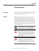
Chapter 1 Features Figure 1 - Features Front View Top View Ethernet Connectors RJ-45 Module Status LEDs Ethernet/IP Network Activity Front Port Link LEDs Rear Port Link DeviceNet Network Status LED Side View Rear View DeviceNet Connector DIN Rail Mounting Panel Mounting Earth Ground Connector Installation The EtherNet/IP Communications Auxiliary may be DIN Rail or panel mounted. To avoid overheating, the unit must be mounted vertically and requires 37.4 mm (1-1/2 in.
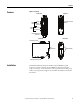
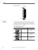
Chapter 1 Figure 2 - Installation Front View 37.44 mm (1-1/2 in.) 37.44 mm (1-1/2 in.) Wiring The EtherNet/IP Communications Auxiliary can accept all forms of DeviceNet cable. However, DeviceNet shielded cable is recommended. The EtherNet/IP Communications Auxiliary complies with the Open Device Vendors Association (ODVA) DeviceNet compliance testing when the distance between end nodes is 100 m or less with 60 or fewer network drops.
Chapter 1 Figure 3 - Wiring Diagram DNET (Black) 24V CAN L (Blue) Shield CAN H (White) DNET (Red) 24V + Earth Ground ATTENTION: Use a shielded DeviceNet cable to comply with CISPR 22 and CISPR 24. Dimensions Figure 4 - Dimension Diagram Dimensions are shown in millimeters (inches). 31.3 (1.23) 110.0 (4.33) 5.85 (0.23) 98.0 (3.86) 100.5 (3.95) 87.0 (3.43) Ø 4.50 (0.16) 105.0 (4.
Chapter 1 Network Design The EtherNet/IP Communications Auxiliary is available as a single Ethernet port (Cat. No. 193-DNENCAT) and dual Ethernet port (Cat. No. 193-DNENCATR) module that has RJ-45 ports to connect to Ethernet cable CAT5 type or better . Rockwell Automation offers a wide variety of Allen-Bradley Ethernet patch cables with its Bulletin 1585 line of Ethernet cables (http://ab.rockwellautomation.com/Connection-Devices/RJ45-NetworkMedia).
Chapter 1 Figure 6 - Ring Ethernet Topology The Cat. No. 193-DNENCATR Module supports Rockwell Automation’s Device Level Ring (DLR) topology as a slave device in which the EtherNet/IP network will still continue to communicate in the event that one of the network chains is disrupted.
Chapter 1 14 Rockwell Automation Publication 193-UM014B-EN-P December 2011
Chapter 2 Configure the EtherNet/IP Communications Auxiliary Introduction This chapter describes how to configure an EtherNet/IP Communications Auxiliary to operate on an EtherNet/IP network. When you first install an EtherNet/IP Communications Auxiliary, the module is Dynamic Host Configuration Protocol (DHCP) enabled. Determining Network Parameters To operate an EtherNet/IP network, you must define these parameters.
Chapter 2 Table 3 - EtherNet/IP Network Parameters for DNS Addressing Network Parameter Description Host Name A host name is part of a text address that identifies the module. The full text address of a module is: host_name.domain_name. Domain Name A domain name is part of a text address that identifies the domain in which the module resides. The full text address of a module is: host_name.domain_name. The domain name has a 48-character limit.
Chapter 2 Figure 7 - Last Octet Selection x 100 Digit x 10 Digit x 1 Digit EXAMPLE When the top dial is set to 1, the middle dial is set to 2, and the bottom dial is set to 3, the resulting IP address is: 192.168.1.123. When the node address selection switches are set to a value greater than 255, the IP address is set to DHCP Enabled or programmed for a static IP address. Assign Network Parameters via the BOOTP/ DHCP Utility By default, the EtherNet/IP Communications Auxiliary is DHCP Enabled.
Chapter 2 3. If appropriate for the network, type the subnet mask, gateway address, primary/secondary server addresses, and domain name in their respective fields. 4. Click OK. The Request History panel displays the hardware addresses of modules issuing BOOTP or DHCP requests. 5. Double-click the MAC address of the module to be configured. NOTE: The MAC address is printed on the front of the EtherNet/IP Communications Auxiliary.
Chapter 2 The New Entry window appears with the module’s Ethernet Address (MAC). 6. Type the IP address, host name, and a module description. 7. Click OK. 8. Cycle power to the module by removing and reapplying the DeviceNet connector. 9. To permanently assign this configuration to the module: Select the module in the Relation List panel and click Disable BOOTP/DHCP. When module power is cycled, it uses the assigned configuration and does not issue a DHCP request.
Chapter 2 4. Select the appropriate subnet to scan for available MAC addresses. 5. Scan the Subnet for all available MAC addresses. 6. Identify the IP address assigned to the MAC ID of the EtherNet/IP Communications Auxiliary. The IP address will have a format that is similar to 192.168.0.100. 7. Open a web browser and type the IP address on the address line to view the internal web server of the EtherNet/IP Communications Auxiliary. 8.
Chapter 2 9. The module will prompt the user for a User Name and Password. Type “Administrator” as the user name, leave the password field blank, then click OK. 10. Assign the appropriate network settings per the recommendation of the network administrator for the network that this module will be communicating on and click Apply. 11. Remove and reapply the DeviceNet connector to allow the communications changes to take affect.
Chapter 2 Other Factors to Consider When Assigning Network Parameters There are other factors to consider when assigning networks parameters, which include the: • network isolation from or integration into the plant/enterprise network. • network size. For large networks, even isolated networks, it might be more convenient and safer to use a BOOTP/DHCP server rather than RSLinx software. The BOOTP/DHCP server also limits the possibility of assigning duplicate IP addresses.
Chapter 2 Behavior of Modules With Duplicate IP Addresses Devices in conflict over an IP address behave differently depending on whether connections have been established to either of the modules and whether both modules support duplicate IP address detection. Table 4 - Device Conflict over Duplicate IP Addresses DNS Addressing If then both modules support duplicate IP address detection, the first started module uses and retains its IP address.
Chapter 2 • embedded in the module OR • the Allen-Bradley EDS file download website. Download the EDS File Embedded in the Module The EDS file for the EtherNet/IP Communications Auxiliary is embedded within the module. After the IP address for the module has been configured, connect the module to same Ethernet network as a personal computer. Using a web browser on the personal computer, a user can download the EDS file using a web browser by following these steps: 1.
Chapter 2 From the EDS File Download Site The EDS file for the EtherNet/IP Communications Auxiliary can also be downloaded from the Allen-Bradley EDS File download site. Using a web browser on the personal computer that is connected to the internet, a user can download the EDS file by following these steps: 1. Type http://www.ab.com/networks/eds on the address line of the web browser. 2. Select EtherNet/IP as the network type, then click Search. 3.
Chapter 2 1. Start the EDS Hardware Installation Tool located at Start>Programs> Rockwell Software>RSLinx Tools. 2. Click Add to register a new device. 3. Click the “Register a single file” radio button, then browse to the location where the EDS file is located. Click Next.
Chapter 2 4. Click Next to accept the installation test results.
Chapter 2 5. Click Next to accept the graphic image. 6. Click Next to register the device.
Chapter 2 7. Click Finish to successfully register the module.
Chapter 2 30 Rockwell Automation Publication 193-UM014B-EN-P December 2011
Chapter 3 Configure the DeviceNet Network Introduction Configuration The purpose of this chapter is to assist in configuring the DeviceNet Network with the EtherNet/IP Communications Auxiliary. A DeviceNet network can be configured using the internal web interface from the EtherNet/IP Communications Auxiliary. 1. From the web page, navigate to Scan List>Configuration>Advanced. 2. If desired, change the baud rate using the DeviceNet Baud Rate pull-down menu.
Chapter 3 3. Type the size of the Scan List I/O Entry in the field. The entry size determines the number of input and output bytes that the EtherNet/IP Communications Auxiliary will scan from each of the scanned devices. The maximum Scan List I/O Entry Size supported is 50 bytes with the default value being 8 bytes. NOTE: Auto Device Replacement (ADR) is discussed in Chapter 6, Automatic Device Recovery or Replace. 4. If necessary, adjust DNet IO Request Packet Interval (RPI) and DNet IO Inhibit.
Chapter 3 6. Change the DeviceNet network address to the appropriate node address, then click Save. NOTE: Typically, DeviceNet scanners have the node address of 0. 7. Click OK to finish changing the scanner DeviceNet network address.
Chapter 3 34 Rockwell Automation Publication 193-UM014B-EN-P December 2011
Chapter 4 Add Devices to the DeviceNet Network Introduction In this chapter, you will be able to assign an address to each DeviceNet module and configure the DeviceNet scanner to scan up to six modules. DeviceNet Node Addressing Each module being added to the DeviceNet network must have a unique network mode address. A unique network node address can be created by using hardware devices (e.g.
Chapter 4 Node Address Basics • Verify the node address assigned to the new device. • Prevent duplicate node address assignments. – When connecting new DeviceNet modules with the Node Commissioning tool from the EtherNet/IP Communications Auxiliary web interface, place one new DeviceNet module on the network at a time. Refer to “New DeviceNet Module” in Table 5 on page 35.
Chapter 4 2. Change the node address using the appropriate mechanism for the new device. Mechanism Procedure Rotary Switch 2 0 PGM 4 2 4 8 6 0 6 MSD LSD Turn the rotary switch dials to the desired node address value. Usually, a small, flathead screwdriver is needed to turn the dials. Once the device is powered up, the rotary switch settings are recognized.
Chapter 4 1. From the EtherNet/IP Communications Auxiliary web page, navigate to Scan List>Configuration>Node Commissioning. 2. Select the device where node address needs to be assigned. Once selected, the Current Settings aand New Settings areas are populated. 3. Double-click the “Node address” field’s value. The value will be highlighted in blue.
Chapter 4 4. Using the keypad on the PC keyboard, change the network node address to the desired value. Ensure the desired value is not duplicating any other device’s node address, then click the Apply button. 5. The following window will appear confirming a successful node address value change. Click OK. 6. Verify the node address was changed to the desired value in the “New settings” section of the page.
Chapter 4 Add DeviceNet Modules to the Scan List After each DeviceNet device has been assigned a unique node address, up to six DeviceNet devices can be added to the EtherNnet/IP Communications Auxiliary DeviceNet scan list. The EtherNet/IP Communications Auxiliary provide two methods to configure the scan list, Simple and User-Defined. Simple 1. From the EtherNet/IP Communications Auxiliary web page, navigate to Scan List>Configuration>Scan List.
Chapter 4 3. Click OK to complete the configuration. The DeviceNet scanner on the EtherNet/IP Communications Auxiliary will begin scanning the DeviceNet devices. User-Defined If there are more than six DeviceNet devices on the network, the user can select up to six DeviceNet devices to scan. Follow the steps below to select specific DeviceNet devices for the scan list. 1. From the EtherNet/IP Communications Auxiliary web page, navigate to Scan List>Configuration>Scan List.
Chapter 4 3. Click >> to move the selected device into the Scan List. 4. Repeat steps 2 and 3 to add five additional DeviceNet devices. 5. Click Save at the bottom right of the screen. 6. Click OK to complete the scan list configuration.
Chapter 5 View & Configure Parameters Introduction In this chapter, you will be able to view and configure parameters for a DeviceNet device that supports the full implementation of the Parameter Object. View & Edit The EtherNet/IP Commuications Auxiliary is able to view and configure parameters for a DeviceNet device that supports the full implementation of the Parameter Object. Users can use the web interface to view and edit parameters for a DeviceNet Module in the scan list.
Chapter 5 2. Click on the Identity folder. The Identity tab will appear, providing information about the selected device. 3. Click on the Parameter folder. Subfields for this folder will appear.
Chapter 5 4. Select a parameter group. A list of up to 15 parameters will be displayed. If more than 15 parameters are available, select the page number or use the navigation arrows to view the additional parameter screens. TIP To increase the update rate of the data being displayed on the screen, lower the value in the “Seconds before refresh:” field. 5. Select a parameter group that contains programmable parameters, then click the Edit button. The value options will appear.
Chapter 5 6. Click the down arrow on the pull-down boxes to adjust fixed values and/or enter numerical values in the fields without an arrow to adjust the values. 7. Click Apply once all parameter edits have been completed. The EtherNet/ IP Communications Auxiliary will download the new parameter values to the device. A confirmation window will appear. 8. Click OK. 9. Continue editing the remaining parameters, if desired.
Chapter 6 Automatic Device Recovery or Replace Introduction In this chapter, using the Automatic Device Recovery or Replace (ADR) will be explained. The use of this feature reduces downtime if a device needs to be replaced. With ADR, there is no need for software tools to get a replacement device configured and online. The EtherNet/IP Communications Auxiliary automatically configures the replacement device if the device was listed in the scan list and the appropriate electronic keying was selected.
Chapter 6 By default, the Device Type, Vendor, and Product Code will be enabled. Electronic keying will define how closely a replacement device must match a failed device before the EtherNet/IP Auxiliary reconfigures a module. If the new module does not match the criteria of one of the checked boxes, the ADR will not function and an ADR error will appear. 3. Once the scan list and DeviceNet module programmable parameters have been configured, click Upload ADR Data.
Chapter 6 5. Click Save, then cycle power on the EtherNet/IP Communications Auxiliary. An ADR download is performed immediately before an I/O connection is allocated by the DeviceNet master. If the download is unsuccessful, an “ADR Error” for the appropriate node will be reported in the corresponding “Scan List Entry Status Word”.
Chapter 6 key is detected on node 63, the EtherNet/IP Communications Auxiliary will attempt to change the module’s network node address to that of the missing scan list node number. When successful, the EtherNet/IP Communications Auxiliary will download the ADR information to the module.
Chapter 7 Automation Controller Communications Introduction This chapter describes and gives examples of how each type of EtherNet/IP messaging, I/O messaging and Explicit messaging, is used. Ethernet Messaging The EtherNet/IP Communications Auxiliary supports two types of EtherNet/IP messaging. • I/O Messaging — Used for deterministic EtherNet/IP communications with ControlLogix™, CompactLogix™, SoftLogix™, and EtherNet/IP scanners. Its primary use is to read and write I/O data for control purposes.
Chapter 7 1. Select File>New from the RSLogix 5000. 2. Select the controller type, chassis type, slot number, and project path. Then, enter a name for the controller and click OK. 3. Right-click the I/O Configuration folder, then select New Module. The Select Module Type window will appear.
Chapter 7 4. Select the desired EtherNet/IP scanner module, then click OK. 5. Enter the desired communication settings, then click Finish. EtherNet/IP Network Configuration with Add-On Profiles After the controller configuration, the EtherNet/IP Communications Auxiliary has to be added to the I/O configuration.
Chapter 7 1. Place the program in offline mode. 2. Right-click on the EtherNet/IP scanner within the I/O Configuration folder, then select New Module to open the Select Module Type window. 3. Select the appropriate device (either 193-DNENCAT or 193DNENECATR, then click OK.
Chapter 7 4. Enter a name for the EtherNet/IP Communications Auxiliary. The name will create tags in RSLogix 5000 that can be used to read and write data from DeviceNet modules being scanned by the EtherNet/IP Communications Auxiliary. 5. Enter the IP address of the EtherNet/IP Communications Auxiliary. 6. Select Change to select a motor protection device with predefined tag names for Data Mapping. For non-motor protection devices, select Generic.
Chapter 7 8. Click OK at the next window to have RSLogix 5000 create the predefined tags. The EtherNet/IP Communications Auxiliary will now show as a module in the I/O Configuration folder. Accessing Module Data with Add-On Profiles With both the Logix controller and EtherNet/IP network configured, the Logix controller can exchange data with the EtherNet/IP Communication Auxiliary. 1. Open the Controller Tags window. 2. Select the Monitor Tags tab.
Chapter 7 ControlLogix Generic Configuration An existing project can be used or a new project can be created to configure EtherNet/IP I/O Messaging. To create a new project, perform the following steps. 1. Select File>New from the RSLogix 5000. 2. Select the controller type, chassis type, slot number, and project path. Then, enter a name for the controller and click OK. 3. Right-click the I/O Configuration folder, then select New Module. The Select Module Type window will appear.
Chapter 7 4. Select the desired EtherNet/IP scanner module, then click OK. 5. Enter the desired communication settings, then click Finish. EtherNet/IP Generic Module Configuration Once the Logix controller has been configured, the EtherNet/IP Communications Auxiliary must be added to the I/O configuration.
Chapter 7 1. Place the program in offline mode. 2. Right-click on the EtherNet/IP scanner within the I/O Configuration folder, then select New Module to open the Select Module Type window. 3. Select Generic Ethernet Module, then click OK.
Chapter 7 4. Enter a name for the EtherNet/IP Communications Auxiliary. The name will create a tag in RSLogix 5000 that can be used to read and write data from the devices being scanned by the EtherNet/IP Communication Auxiliary. 5. Select Data-INT for the Comm Format. The Data-INT format wil l represent the data from the EtherNet/IP Communications Auxiliary as a field of 16-bit values. 6. Set the Connection Parameters. I/O data is accessed using Input Instance 101 and Output Instance 100.
Chapter 7 7. Type the IP address of the EtherNet/IP Communications Auxiliary. 8. Type the value for the time between each scan of the module. The recommended RPI time is 250 ms. Ensure that the Inhibit Module is not checked. 9. Click OK to add the EtherNet/IP Communications Auxiliary to the I/O Configuration in RSLogix 5000.
Chapter 7 2. Open the Controller Tags window. 3. Select the Monitor Tags tab. An array of input and output tags were generated for each of the six scanned devices. To control the output relays for the scanned device, use the output tags; to obtain diagnostic information from the scanned device, use the input tags. The format of output data is shown in the table to follow. Table 6 - Output Assembly — Instance 100 Byte Size Contents Scan List I/O Size Data to be delivered to the first scan list entry.
Chapter 7 Byte Size Contents Scan List I/O Size Produced I/O data from the fourth scan list entry. Scan List I/O Size Produced I/O data from the fifth scan list entry. Scan List I/O Size Produced I/O data from the sixth scan list entry.
Chapter 7 In the screen capture below, the user-defined structure listing the integers is being returned in this example.
Chapter 7 2. Set up the MSG instruction in the Configuration tab to read the list of attributes (Parameters Group) by configuring the following fields: • Message Type: CIP Generic • Service Type: Custom • Service Code: 0x03 (hex) • Class: 0x375 (hex) • Instance: 1 (dec) • Attribute: 0x00 (hex) • Source Element: MSG_Read_Request [0] • Source Length: 14 (bytes) • Destination: MSG_Read_Data 3.
Chapter 7 4. Click OK. When finished, the MSG instruction will read the 25 parameters from the E3 Overload Relay and place the results into MSG_Read_Data as shown below.
Chapter 8 E-mail/Text Introduction This chapter describes e-mail notifications and how to configure an EtherNet/IP Communications Auxiliary to send e-mail messages and text notifications for different communication events. E-mail Notifications Events Several communication events can trigger e-mail notifications. These events are fault conditions for the DeviceNet scan list and EtherNet/IP Communications Auxiliary.
Chapter 8 EXAMPLE E-mail Subject: 193-DNENCATR Comms Aux has detected a fault E-mail Body: Fault Status: Device Name: 193-DNENCATR Comms Aux Device Description: Motor Starters Device Location: Bay 6-U29 Contact Info: Contact Person contactperson@thecontact.com The first word in the e-mail subject is the device name. If a device name is not configured, then the product name attribute from the identity object will be used.
Chapter 8 3. Log in with the username “Adminstrator”, leave the password field blank, and click OK. NOTE: If desired, a password can be set within the Administrative Settings tab. 4. Type the information into the e-mail notification fields as stated below. E-mail Recipient The e-mail address of the person who will receive the notifications. E-Mail Sender The e-mail address from which the notification will be sent. SMTP Server Consult with the network administrator for the SMTP server address.
Chapter 8 2. Type the Device Identity information into the fields as described below. Device Name The name of the EtherNet/IP Communications Auxiliary. Device Description The description of the EtherNet/IP Communications Auxiliary. Device Location The location of the EtherNet/IP Communications Auxiliary. Contact Information The contact information for the EtherNet/IP Communications Auxiliary. Device X Name The name of the DeviceNet device being scanned.
Chapter 8 Multiple e-mail addresses can be entered into the E-mail Recipient field, separating each e-mail address with a semicolon (;). The E-mail Recipient field is limited to 255 characters. EXAMPLE Limitations An EtherNet/IP Communications Auxiliary sending an e-mail and text message when a Communications Timeout event occurs: Based on the functionality of the EtherNet/IP Communications Auxiliary, there are some limitations on when the e-mails can be triggered.
Chapter 8 72 Rockwell Automation Publication 193-UM014B-EN-P December 2011
Chapter 9 Device Parameters Introduction The EtherNet/IP Communications Auxiliary provides parameters to allow the user to view the status and configure the DeviceNet scanner with RSNetWorx for DeviceNet if the user does not want to use the internal web server of the EtherNet/IP Communications Auxiliary. The 14 available parameters are listed below.
Chapter 9 Table 10 - Parameter 2 — SL Entry 1 Status Value Description Access Rule Data Type Provides the status of the first scan list entry in the DeviceNet scanner. Get WORD Units Min. Max.
Chapter 9 Table 13 - Parameter 5 — SL Entry 4 Status Value Description Access Rule Data Type Units Provides the status of the fourth scan list entry in the DeviceNet scanner. Get WORD — Min. Max.
Chapter 9 Table 16 - Parameter 8 — SL Entry Size Value Description Access Rule Data Type Units Defines the number of bytes to be scanned for I/O data from each DeviceNet Device. Get/Set USIN T Bytes Min. Max. Default 1 50 8 Table 17 - Parameter 9 — Device Keys Value Description Access Rule Data Type Determines how electronic keying will be performed. Get/Set USIN T Units Min. Max.
Chapter 9 Table 21 - Parameter 13 — DNet IO RPI Value Description Defines the requested packet interval rate in milliseconds used on DeviceNet Polled I/O messaging. Access Rule Data Type Units Min. Get/Set WORD ms 2 Max. Default 1000 75 Table 22 - Parameter 14 — DNet IO Inhibit Value Description Defines the inhibit time in milliseconds used on DeviceNet Change of State (COS) I/O messaging. Access Rule Data Type Units Min.
Chapter 9 78 Rockwell Automation Publication 193-UM014B-EN-P December 2011
Chapter 10 Troubleshooting Introduction The purpose of this chapter is to assist in troubleshooting the EtherNet/IP Communications Auxiliary. SHOCK HAZARD: Servicing energized industrial control equipment can be hazardous. Electrical shock, burns, or unintential actuation of controlled industrial equipment may cause death or serious injury .
Chapter 10 Power-Up Reset Mode Figure 8 - Status LEDs Module Status (MS) LED Ethernet/IP Network Status (NS) LED Front Port Link Activity LED Rear Port Link Activity LED DeviceNet Network Status (NS) LED During the Power-Up Reset Mode, the following procedure occurs. 1. The various LEDs will cycle simultaneously. • Module Status (MS) LED will flash green for approximately 0.25 seconds, flash red for another 0.25 seconds, then remain a solid green.
Chapter 10 4. If the power-up or reset is successful, the overload relay will enter into Run Mode. Run Mode In Run Mode, the EtherNet/IP Communications Auxiliary will: • operate as a slave device to a master device on an EtherNet/IP network. • operate as a master device and scan up to six slave devices on a DeviceNet network. • accept messages from a master on the EtherNet/IP network. • send response messages, COS messages, or CYCLIC messages to a master.
Chapter 10 Recoverable Error Mode In this mode, the EtherNet/IP Communications Auxiliary MS LED flashes red. The device will respond to messages that are specified in offline mode recovery message protocol. Error Type Description LED State Recoverable Duplicate IP address detected. Flashing Red A device is not present on the DeviceNet scan list. Unrecoverable Error Mode In this mode, the EtherNet/IP Communications Auxiliary MS LED illuminates a solid red.
Chapter 10 Status LED DeviceNet Network Status (NS) Color State Possible Cause Corrective Action None — The EtherNet/IP Communications Auxiliary is not receiving power. Check the DeviceNet cable connections and verify that 24V DC exists between the red and black terminals. Green, Red, Not Illuminated Flashing (once) Normal This is a normal power-up sequence. Green Flashing The EtherNet/IP Communications Auxiliary is not configured to scan any DeviceNet slave devices.
Chapter 10 84 Rockwell Automation Publication 193-UM014B-EN-P December 2011
Appendix A Specifications Specifications Table 24 - Ratings Terminal Ratings Terminal Screw M3 Wire Cross Section See wiring diagram section Torque 0.56…0.79 N•m (5…7 lb.•in.) Degree of Protection IP20 Power Supply Ratings Rated Supply Voltage Us 24V DC Rated Operating Range Ue 24V -15%, +10% DC Rated Supply Current Ie 100 mA at 24V DC Maximum Surge Current at Power-Up 6.4 A Maximum Power Consumption 2.
Appendix A Table 25 - Electromagnetic Compatibility Electromagnetic Compatibility Electrostatic Discharge Immunity Test Level Performance Criteria RF Immunity Test Level Performance Criteria Electrical Fast Transient/Burst Immunity Test Level 8 kV Air Discharge 4 kV Contact Discharge B➊➋ 10V/m: 80 MHz…1 GHz 3V/m: 1.4 GHz…2 GHz 1V/m: 2.0 GHz…2.
Appendix A Table 27 - Standards & Certifications Standards and Certifications UL 508 CSA 22.2, No.
Appendix A 88 Rockwell Automation Publication 193-UM014B-EN-P December 2011
Appendix B EtherNet/IP & DeviceNet Information Electronic Data Sheet (EDS) Files EDS files are specially formatted ASCII files that provide all of the information necessary for a configuration tool (e.g., RSNetWorx for EtherNet/IP) to access and alter the parameters of a device. The EDS file contains all the parameter information of a device: number of parameters, groupings, parameter name, min, max, and default values, units, data format and scaling.
Appendix B Table 29 - Identity Object Class Attributes Attribute ID Access Rule Name Data Type Value 1 Get Revision UINT 0x0001 2 Get Max. Instance UINT 0x00011 Identity Object instances contain the following instance attributes.
Appendix B DeviceNet Object — CLASS CODE 0x03 The following class attributes will be supported for the DeviceNet Object. Table 32 - DeviceNet Object Class Attributes Attribute ID Access Rule Name Data Type Value 1 Get Revision UINT 2 A single instance of the DeviceNet Object will be supported by the following attributes.
Appendix B Table 36 - Instance Attributes # Access Name Type 3 Get/Set Data Value Description Array of UINT — Data produced/consumed by the module Output Assemblies The following output assembly instances are implemented. Table 37 - Instance 100 Byte Size Contents Scan List I/O Size Data to be delivered to the first scan list entry. Scan List I/O Size Data to be delivered to the second scan list entry. Scan List I/O Size Data to be delivered to the third scan list entry.
Appendix B Table 39 - Instance 103 ➊ Byte Size Contents 4 Bytes Logix Status Word 4 Bytes DeviceNet Scanner Status (Parameter 1) See Table 9 on page 73 4 Bytes Scan List Entry 1 Status Word (Parameter 2) See Table 10 on page 74 4 Bytes Scan List Entry 2 Status Word (Parameter 3) See Table 11 on page 74 4 Bytes Scan List Entry 3 Status Word (Parameter 4) See Table 12 on page 74 4 Bytes Scan List Entry 4 Status Word (Parameter 5) See Table 13 on page 75 4 Bytes Scan List Entry 5 Status Word (P
Appendix B Configuration Assembly Table 40 - Instance 102 (Revision 1) 94 Byte Size Contents 2 Bytes Revision = 1 2 Bytes ScanList I/O Size 2 Bytes Data Link Update Interval (ms) 1 Byte Data Link 1 Node 2 Bytes Data Link 1 Parameter 1 Byte Data Link 2 Node 2 Bytes Data Link 2 Parameter 1 Byte Data Link 3 Node 2 Bytes Data Link 3 Parameter 1 Byte Data Link 4 Node 2 Bytes Data Link 4 Parameter 1 Byte Data Link 5 Node 2 Bytes Data Link 5 Parameter 1 Byte Data Link 6 Node 2 Byte
Appendix B Table 41 - Instance 102 (Revision 2)➊ Byte Size Contents 2 Bytes Revision = 2 2 Bytes ScanList I/O Size 2 Bytes Data Link Update Interval (ms) 2 Bytes Reserved 2 Bytes Data Link 1 Node 2 Bytes Data Link 1 Parameter 2 Bytes Data Link 2 Node 2 Bytes Data Link 2 Parameter 2 Bytes Data Link 3 Node 2 Bytes Data Link 3 Parameter 2 Bytes Data Link 4 Node 2 Bytes Data Link 4 Parameter 2 Bytes Data Link 5 Node 2 Bytes Data Link 5 Parameter 2 Bytes Data Link 6 Node 2 Bytes
Appendix B Table 43 - Connection Manager Object Common Services Implemented for: Instance Service Name Yes Forward Open Yes Forward Close Yes Unconnected Send Parameter Object — CLASS CODE 0x0F The following class attributes are supported for the Parameter Object.
Appendix B Attribute ID Access Rule Name Data Type 18 Get Divisor Link UINT 19 Get Base Link UINT 20 Get Offset Link UINT 21 Get Decimal Precision USINT Value Parameter Dependent The following commons services are implemented for the Parameter Object.
Appendix B QoS Object — CLASS CODE 0x48 The following class attributes will be supported for the QoS object. Table 49 - QoS Object Class Attributes Attribute ID Access Rule Name 1 Get Data Type Value Revision UINT 1 A single instance (Instance 1) will be supported.
Appendix B Port Object — CLASS CODE 0x0F4 The Port object supports the following class attributes. Table 53 - Port Object Class Attributes Attribute ID Access Rule Name Data Type Value 1 Get Revision UINT 1 2 Get Max. Instance UINT 2 3 Get Num. Instances UINT 2 8 Get Entry Port UINT 1 9 Port Instance Info Array of 1 Structure of Get Port Type UINT Port Number UINT Two instances of the Port object will be supported.
Appendix B TCP/IP Interface Object — CLASS CODE 0xF5 The TCP/IP object supports the following class. Table 56 - TCP/IP Object Class Attribute ID Access Rule Name 1 Get Data Type Value Revision UINT 3 For single port devices, one instance of the TCP/IP interface object is supported. For dual port devices, two instances of the TCP/IP interface object are supported.
Appendix B Table 58 - TCP/IP Interface Object Common Services Implemented for: Service Code Class Instance Service Name 0x01 No Yes Get_Attributes_All 0x0E Yes Yes Get_Attribute_Single 0x10 No Yes Set_Attribute_Single Ethernet Link Object — CLASS CODE 0xF6 The following class attributes are supported for the Ethernet Link object.
Appendix B Attribute ID Access Rule Name Data Type 6 Get/Set Interface Control Struct of: Control Bits Forced Interface Speed 7 Get Interface Type USINT 8 Get Interface State USINT 10 Get Interface Label SHORT_STRING Value Instance 1: Port 1 Instance 2: Port 2 The following common services are implemented for the Ethernet Link object.
Rockwell Automation Support Rockwell Automation provides technical information on the Web to assist you in using its products. At http://www.rockwellautomation.com/support/, you can find technical manuals, a knowledge base of FAQs, technical and application notes, sample code and links to software service packs, and a MySupport feature that you can customize to make the best use of these tools.