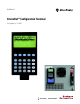
User Manual DeviceNet™ Configuration Terminal Catalog Numbers 193-DNCT
™ Configuration Terminal
Important User Information Because of the variety of uses for the products described in this publication, those responsible for the application and use of this control equipment must satisfy themselves that all necessary steps have been taken to assure that each application and use meets all performance and safety requirements, including any applicable laws, regulations, codes and standards.
Manual Objectives The purpose of this manual is to provide you with the information necessary to apply the DeviceNet™ Configuration Terminal. Described in this manual are methods for installing, configuring, and troubleshooting the DeviceNet™ Configuration Terminal. IMPORTANT Read this manual in its entirety before installing, operating, servicing, or initializing the DeviceNet™ Configuration Terminal.
Important User Information . . . . . . . . . . . . . . . . . . . . . . . . . . . . . . . . . . . . . . . European Communities (EC) Directive Compliance. . . . . . . . . . . . . . . . . Manual Objectives . . . . . . . . . . . . . . . . . . . . . . . . . . . . . . . . . . . . . . . . . . . . . . . . Who Should Use This Manual . . . . . . . . . . . . . . . . . . . . . . . . . . . . . . . . . . . . . Vocabulary . . . . . . . . . . . . . . . . . . . . . . . . . . . . . . . . . . . . . . . . . . . . . . . . . . .
Table of Contents Chapter 6 Parameter Choices Menu Parameter Choices Menu . . . . . . . . . . . . . . . . . . . . . . . . . . . . . . . . . . . . . . . . . Groups Screen . . . . . . . . . . . . . . . . . . . . . . . . . . . . . . . . . . . . . . . . . . . . . . . . . . . Num List Selection . . . . . . . . . . . . . . . . . . . . . . . . . . . . . . . . . . . . . . . . . . . . . . . Parameter Edit Screens. . . . . . . . . . . . . . . . . . . . . . . . . . . . . . . . . . . . . . . . . . . .
Table of Contents Chapter 12 DeviceLogix™ Functionality DeviceLogix™ Functionality . . . . . . . . . . . . . . . . . . . . . . . . . . . . . . . . . . . . . . . DeviceLogix™ Choices Menu . . . . . . . . . . . . . . . . . . . . . . . . . . . . . . . . . . . . . . DeviceLogix™ Monitor. . . . . . . . . . . . . . . . . . . . . . . . . . . . . . . . . . . . . . . . . . . . Boolean Gates: . . . . . . . . . . . . . . . . . . . . . . . . . . . . . . . . . . . . . . . . . . . . . . .
Table of Contents Chapter 17 Terminal Setup Menu Terminal Setup Menu . . . . . . . . . . . . . . . . . . . . . . . . . . . . . . . . . . . . . . . . . . . . Communication Setup Screen (HIM Comm) . . . . . . . . . . . . . . . . . . . . . . Password Menu . . . . . . . . . . . . . . . . . . . . . . . . . . . . . . . . . . . . . . . . . . . . . . . . . . Password Setup (Primary) . . . . . . . . . . . . . . . . . . . . . . . . . . . . . . . . . . . . . Password Setup (Secondary) . . . . . . . . . . . . . . . .
Chapter 1 Product Overview Product Overview The 193-DNCT product is a handheld device that can be used to commission, configure, program, and monitor other devices on a DeviceNet™ network. In addition, the 193-DNCT can be used to upload, store, and later download complete device configurations for DeviceNet™ devices via the network. The 193-DNCT also has the capability to present DeviceNet™ physical layer diagnostics and network bandwidth statistics to the user.
Chapter 1 Product Overview Notes: 6 Rockwell Automation Publication 193-UM009B-EN-P - February 2013
Chapter 2 Installation and Wiring Installation and Wiring The DNCT ships complete with a 1 m cable (193-CB1) for connection to a DeviceNet™ network. This cable has a plug connection to the terminal on one end, and color coded bare leads on the other end. Alternately, a 1 m cable (193CM1) can be ordered that has a plug connection to the terminal on one end, and a DeviceNet™ male micro style connector on the other end.
Chapter 2 Installation and Wiring 193-DNCT-BZ1 Physical Connections ATTENTION: When mounting in a door or panel-mounted bezel kit, only the Cat. No. 193-DNCT-BZ1 DeviceNet™ Bezel Kit should be used with the Bulletin 193-DNCT DeviceNet™ Configuration Terminal. The optional Cat. No. 193-DNCT-BZ1 connects to the DeviceNet™ network via an attached cable that has color coded bare leads.
Chapter 3 Physical Features Physical Features Figure 1 - Cat. No. 193-DNCT Physical Features 8-Line, 21-Character, Backlit LCD Display Navigation Keys Function Keys Numeric Entry Keys Communication Port Reset Key Communication Port The communication port is used to connect the DNCT to a DeviceNet™ network through use of a communication cable or bezel mount kit (Cat. No. 193DNCT-BZ1). Additionally, 24V DC power is provided to the DNCT at the communication port.
Chapter 3 Physical Features Key Descriptions Escape Key. Exit a menu or cancel a change. Select key. Select a value, digit, or screen choice. Increment key. Scroll through options, increase a value, or toggle a bit. Decrement key. Scroll through options, decrease a value, or toggle a bit. Enter key. Enter a menu, enter a mode, or enter a value. Scroll left or right keys. Scroll left or right through a value. Shift key. Small values (yellow text) on top of keys are entered when pressed after the shift key.
Chapter 4 Quick Start Powerup The DeviceNet™ Configuration Terminal is shipped so that when it is placed on the network for the first time, it will automatically set its baud rate to that of the traffic on the network, and then assign itself an unused network address.
Chapter 4 Quick Start Terminal Setup Enable = AutoBaud enabled Disable = Use fixed Baud Rate Enable = Auto addressing on power up Disable = Use fixed network address Fixed Baud Rate setting Fixed Address setting OR the starting address for auto address Powerup delay in seconds To scroll through the items on the screen, press the SEL key. To change the value of a selected item, press the Increment or Decrement key. To commit the new value for use, press the Enter (return arrow) key.
Quick Start Chapter 4 Version: Displays Version information for the selected device. Params: Provides access to configuration and status parameters for the selected device. Allows the operator to search for parameters that are not at factory defaults. Copy Cat: Upload and store complete device configurations, including DeviceLogix™ programs to the programming terminal’s memory. Download stored device configurations from the programming terminal memory to the selected device.
Chapter 4 Quick Start Change a parameter value by first pressing the SEL key and then modifying the selected value. 1) Press the SEL key to select the value 2) The Increment and Decrement keys increment or decrement the value when it is selected. An edit box will appear when a key is pressed. OR Enter a number from the numeric keypad. An edit box will appear when a key is pressed. Pressing the Enter key will write the new value to the selected device.
Quick Start Chapter 4 The 193 DeviceNet™ Configuration Terminal often refers to itself as a HIM (Human Interface Module).
Chapter 4 Quick Start Who Menu Display The Who Menu displays the device information for devices that support a DeviceNet™ sub net. When the +DeviceNet Subnet choice is selected and the Enter key is pressed, the Subnet Who Menu will be displayed. Selecting a device at the Subnet Who menu and pressing the Enter key will display all of the menus available at the standard Who menu.
Chapter 5 Device Choices Menu Device Choices Menu The Device Choices menu is entered from the Network Who screen when a device is selected and the Enter key is pressed. This menu allows the operator to choose what operation is to be performed on the selected device. The choices on this menu are only displayed for features that the selected device supports. The Inc and Dec keys allow the operator to move up and down through the selections. The Enter key will advance to the selected menu.
Chapter 5 Device Choices Menu Standard Device Status Menu The 193-DNCT displays the following menu for devices that do not support the Fault or Warning Object.The Identity Object Status Attribute (5) is monitored continuously when viewing this menu. The display is updated to reflect the status of the device.
Device Choices Menu Chapter 5 Figure 1 - Fault Buffer with all optional attributes supported with a fault present. Fault code number and name Use the INC/ DEC keys to move thru the Fault Buffer. The Device is currently faulted and the buffer entry is reported as trip fault.
Chapter 5 Device Choices Menu keypad can be used to attempt to clear the current warning by sending a clear warning command to the devices Warning Object. Warning code number and name Warning code number and name Figure 3 - Warning Buffer without optional attributes supported Use the SEL key to move back and forth from the Buffer number to the Clear Buffer Command. With the Clear Buffer choice highlighted, press the Enter key to clear the buffer.
Chapter 6 Parameter Choices Menu Parameter Choices Menu The Parameter Choices Menu is only available if the selected device has built-in parameter support (DeviceNet™ Parameter Object). This menu allows the operator to go to screens that monitor and change parameters, view/select parameter groups, and search for parameters that are not at their default settings. The Inc and Dec keys allow the operator to move up and down through the selections. The Enter key advances the user to the selected item.
Chapter 6 Parameter Choices Menu Parameter Edit Screens The Parameter Edit Screens allow the device’s parameters to be monitored and edited. The parameter screens have slightly different formats for each parameter data type (numeric, value enumerated, bit enumerated Boolean, etc.) Numeric Parameters Numeric parameter values are displayed as follows: Parameter number Paramete r name Parameter units Indicates that this parameter is Read Only and its value cannot be edited.
Parameter Choices Menu Chapter 6 parameters. Entering a new parameter number directly can be done by entering a number with the numeric keypad (only if accessed through the Num List). Current parameter number Pressing a numeric key will displayed an edit box to enter a new parameter number in. Changing a Parameter Value Changing a parameter value is done by pressing the Sel key to highlight the parameter value then using the Inc/Dec keys or numeric keys to enter the value.
Chapter 6 Parameter Choices Menu parameter value is selected, pressing the Esc key will deselect the parameter value and allow the parameter number to be changed.
Parameter Choices Menu Enumerated Parameters Chapter 6 Parameters that display Value Enumerated data values appear as follows: Enumerated Parameter value To change a value, press the Sel key to select the Enumerated Parameter value, then use the Inc/Dec key to change the value Rockwell Automation Publication 193-UM009B-EN-P - February 2013 25
Chapter 6 Parameter Choices Menu Parameters with Bit Enumerated data values are displayed as follows: Bit enumerated parameter value Bit selected Text string associated with the selected bit Press the left/right arrow key to select the next bit Floating Point Parameters 26 Parameters with Floating Point values will be displayed as follows: Rockwell Automation Publication 193-UM009B-EN-P - February 2013
Parameter Choices Menu Chapter 6 Entering floating point numbers is performed much the same as regular numeric parameters described earlier. The exponential (displayed as an “E”) is entered as follows: Use the Shift key then the Exp key to add the E into the value when editing a floating point value Search for Changed Parameters This function is invoked by selecting the Search option from the Parameter Choices Menu.
Chapter 6 Parameter Choices Menu Parameter Display-Value Enumerated 28 Certain parameters have enumerated values that are not bit enumerated values, the following screen is displayed and shows the “Raw Value” of the enumerated value.
Chapter 7 Copy Cat Menu Copy Cat The copy cat menu allows the operator to upload and download complete device configurations to and from the Configuration Terminal. For DeviceNet™ slave devices, these complete device configurations consist of all configuration parameter values and any DeviceLogix™ program that is programmed in the device. For Allen-Bradley DeviceNet™ Scanners, device configurations consist of the scan list.
Chapter 7 Copy Cat Menu first screen will allow the operator to select where the data will be stored, either to an existing file or a new file: Existing Copy Cat file names Selected file New unnamed “empty” file After selecting a file, you will be able to name/rename it: Selected Character; use the Sel key to move the cursor to the right to select the next character File name the Copy Cat data will be saved to Use the Inc/Dec key to move the cursor to change the character.
Copy Cat Menu Chapter 7 Once the parameters are uploaded, the DeviceLogix™ program will be uploaded (if applicable): Currently uploading the Logix program When the upload is complete, the screen will appear as follows: Copy Cat Downloading To download complete device configuration files that have been stored in the Configuration Terminal, select HIM->Dev at the Copy Cat Menu.
Chapter 7 Copy Cat Menu After selecting the file to download, press the Enter key to start the download. If the device being downloaded to does not match the device the file was uploaded from, an error is displayed before the download continues: Mismatch type. This could be: Vendor ProdType ProdCode Revision IMPORTANT Pressing the Enter key will cause the Configuration Terminal to ignore the electronic keying errors and continue the download.
Copy Cat Menu Chapter 7 If there are errors during the download process, the screen will look like this: Errors may occur in either or both parameters and/or the DeviceLogix™ program downloading If parameter errors occur, pressing the Enter key will bring up the following screen, which will allow the operator to choose to view the parameters that had errors during the download. Note: Only the first 32 parameters with errors are stored.
Chapter 7 Copy Cat Menu When a Copy Cat data file is downloaded to a different firmware revision of the same product, the user is made aware of the revision difference as follows: Pressing the Enter key will cause the Configuration Terminal to ignore the revision difference and continue the download Pressing ESC will cause the download to be aborted In some products, new firmware revisions were released in order to add DeviceLogix™ capability to the product.
Copy Cat Menu Chapter 7 current range is different from that of the product that the data file was uploaded from, the following screen appears: Pressing the Enter key will cause the Configuration Terminal to ignore the product code (current range) Pressing ESC will cause the download to be aborted When downloading to devices in the same product family with different current ranges, the download results will often include Parameter Errors.
Chapter 7 Copy Cat Menu Deleting Copy Cat Files Deleting a Copy Cat file from the memory of the Configuration Terminal is done by selecting the Delete option at the Copy Cat Choice menu. Select the file name to delete, and press the Enter key to delete the file. If all the files have been deleted, the screen will again display the Copy Cat Choice menu, but the Delete and HIM -> Dev options will not be displayed.
Chapter 8 Tools Menu Tools Menu The Tools Menu gives the user access to the Node Commissioning screen, a Class Instance Attribute editor, Graphical parameter chart recorder screen, Assembly menu, and Heartbeat menu. The Tools Menu is shown below: Node Commissioning Pressing Enter while the NodeComm item is selected in the Tools Menu invokes the Node Commissioning screen. Node commissioning allows the operator to change the Mac ID and/or the baud rate for the currently selected device.
Chapter 8 Tools Menu The Get service is outlined in the following screen description: Highlight and press the Enter key to CIA Copy and Paste is available for this menu Display size of read data. Choices: Byte, Word, Dword, or Data that is read when a message is requested Selected service The Set service is outlined in the following screen description: : Highlight and press the Enter key to perform the Display size of data to write.
Tools Menu Chapter 8 to an oscilloscope or chart recorder). The first screen allows the operator to configure the four Class, Instance, or Attributes to be monitored. Class, Instance, Attribute to graph, Note: Traces with the class set to zero will not be graphed. Offset is the number of pixels from the bottom of the screen the min value for this trace will be displayed at.
Chapter 8 Tools Menu Graph View Screen This menu displays the CIA data in graphical form. This screen show only one trace configured Pressing the Enter key while the Graph View Screen is displayed stops the trace and displays a cursor that can be used to view the raw value that was read for that point on the graph. The Cursor; pressing the Inc/ Dec key will The raw data value corresponding to a point on the graph where the cursor intersects.
Tools Menu Chapter 8 Pressing the Enter Key at the “Assembly Consumed / Produced” menu will advance the 193-DNCT to the next menu. This menu lists all of the available assemblies to view. The format for the “Assembly List” menu is as follows: The Assemblies Tag Menu is similar to the IO Tags Menu, however, the data for consumed assemblies can be modified if there is no active IO connections present between the device and the PLC.
Chapter 8 Tools Menu Notes: 42 Rockwell Automation Publication 193-UM009B-EN-P - February 2013
Chapter 9 Advanced Functions Menu Advanced Functions Menu The Advanced Functions Menu provides access to a DeviceLogix™ editor, Zone Interlocking Protocol (ZIP) configuration and monitoring screens, an I/O message timing screen that monitors I/O messaging timing between the selected device and a DeviceNet™ scanner, and Discrete I/O statistics.
Chapter 9 Advanced Functions Menu Notes: 44 Rockwell Automation Publication 193-UM009B-EN-P - February 2013
Chapter HeartBeat Menus 10 The HeartBeat feature can be found in the Tools Menu The user can enable or disable the Heartbeat feature and modify the scanning interval from the Setup Menu. The Heartbeat Monitor menu displays the contents of the last received Heartbeat message. The menu is displayed when the Monitor button is pressed on the Heartbeat Choices Menu.
Chapter 10 Notes: 46 Rockwell Automation Publication 193-UM009B-EN-P - February 2013
Chapter 11 I/O Message Monitoring I/O Message Monitoring This screen displays I/O message timing information and I/O message data for the currently selected device. It is accessed by selecting I/O Msg and pressing the Enter key at the Advanced Functions Menu. Press the INC/DEC key to switch between consumed and produced data Type of IO connection.
Chapter 11 I/O Message Monitoring Notes: 48 Rockwell Automation Publication 193-UM009B-EN-P - February 2013
Chapter 12 DeviceLogix™ Functionality DeviceLogix™ Functionality The Configuration Terminal allows the operator to monitor, edit or delete DeviceLogix™ programs for devices that support DeviceLogix™. DeviceLogix™ can also be enabled or disabled for a device. The DeviceLogix™ functions can be accessed through the DeviceLogix™ Choices Menu, which is accessed by pressing Enter from the Advanced Functions Menu while the DevLogix menu item is selected.
Chapter 12 DeviceLogix™ Functionality Boolean Gates: AND, OR, XOR, NAND, NOR, NXOR and NOT Function block number and type Value of input or output Negated (Active Low) inputs IN3 and IN4 may or may not be present Bistable Latches: RS Latch and SR Latch Press the SEL key to highlight the function block’s inputs and outputs text strings.
DeviceLogix™ Functionality Chapter 12 Timers: On Delay, Off Delay and Pulse Timer Time base: 1 mSec or 10 mSec Press the Sel key to highlight the preset or count value. To accept a new value press the Enter key Discrete Output Points (DOPs): The name of what is driving the Discrete Output Point in the Device Logix program Discrete Output Point (DOP).
Chapter 12 DeviceLogix™ Functionality DeviceLogix™ Monitor. To create, edit or delete a program element, use the INC/ DEC keys to navigate to the item to create/edit and then press the Enter key. To edit one of the inputs of a function block, use the SEL key to highlight the input and then press the Enter key. To invoke the DeviceLogix™ Editor, select the Edit item in the DeviceLogix™ Choices Menu and press the Enter key.
DeviceLogix™ Functionality Function Blocks Chapter 12 The 193-DNCT has function blocks available in the DeviceLogix Library. The DeviceLogix Library version 3 and 5 are available with firmware v2.001 and v3.001, respectively. Devices that use the DeviceLogix Library version 3 or later may enable support for an enable line on each function block. An upgrade to the existing Boolean function block displays the enable line, if the device supports this feature. The 193-DNCT Series A v2.
Chapter 12 DeviceLogix™ Functionality Notice that the current source bit assignment for a selected input will be displayed on the screen for three seconds as shown below: The Assignment text will disappear after three seconds To edit an input source bit assignment, press the Enter key while the desired input is selected.
Chapter 13 Discrete I/O Status Discrete I/O Status The Discrete I/O Status screen is displayed by selecting I/O Stat and pressing the Enter key at the Advanced Functions Menu. This screen displays the status of any Discrete Input Points (DIP’s), Discrete Output Points (DOPs) and Produced Network Bits (PNBs) that are implemented in the currently selected device. This screen will be available if any one of the DIPs, DOPs or PNBs are supported in the currently selected device.
Chapter 13 Discrete I/O Status Notes: 56 Rockwell Automation Publication 193-UM009B-EN-P - February 2013
Chapter 14 Zone Interlock Protocol (ZIP) Zone Interlock Protocol (ZIP) The Zone Interlock Protocol (ZIP) menu is available for devices that support the DeviceNet™ Zone Interlock Protocol Object. The Zone Interlock Protocol provides a way for devices to share I/O message data directly, and the data that is consumed from other devices can then be used in a DeviceLogix™ program. The ZIP Choices Menu is displayed by selecting ZIP and pressing the Enter key at the Advanced Functions Menu.
Chapter 14 Zone Interlock Protocol (ZIP) Mapping Consumed ZIP Data This section explains mapping I/O data for a Zone. Assume that the DeviceNet™ Configuration Terminal is currently configuring Node 11 on the Network. Also assume Node 5 is on the network, and is producing I/O data. Node 11 will be configured to consume the I/O data that Node 5 is producing, which will be done by mapping Node 5 I/O data to Zone 1 in the ZIP data table of Node 11.
Zone Interlock Protocol (ZIP) Chapter 14 The following screen shows the EPR (Expected Packet Rate) field highlighted: EPR (Expected Packet Rate) allows the expected packet rate of the I/O data from node (Node 5) to be changed. This value is in milliseconds. The following screen shows the IO Msg field highlighted: Note: The IO Msg field may also be referred to as the Zone Mask field.
Chapter 14 Zone Interlock Protocol (ZIP) Use the Sel key to select the ZIP data table field. Then use the Right/Left arrows to select the second byte (the second “05”) in the data table. The display appears as follows: When each byte in the ZIP data table is highlighted, the bit of the IO Msg field that is Mapped to that byte is also highlighted. As mentioned earlier, use the Sel key to highlight the various ZIP configuration parameters for this zone.
Zone Interlock Protocol (ZIP) Chapter 14 When all edits are complete, the ZIP configuration data must be saved to the device (Node 11 for this example). To save the changes, use the Sel key to highlight the Save field and press the Enter key. When performing a Save, all the configuration data for all Zones is saved.
Chapter 14 Zone Interlock Protocol (ZIP) Press the Right/ Left arrow keys to select the various bytes in the ZIP data table.
Chapter 15 DeviceNet™ Scanner Menu DeviceNet™ Scanner Menu The DeviceNet™ Scanner Menu is available for Allen-Bradley DeviceNet™ scanners. The scanner menus give the operator some basic information about the scanner’s configuration and the ability to adjust a few of the scanner attributes. The scanner menus do not allow the operator to perform complete configuration of a scanner. RSNetWorx for DeviceNet™ must be used for initial scanner configuration for a system.
Chapter 15 DeviceNet™ Scanner Menu AutoScan Function The Auto Scan screen allows the operator to enable and disable the Auto Scan feature of some scanners. This menu will only be available if the scanner supports the Auto Scan function. This line reflects the status of the Processor, IDLE or AutoScan must be Disabled to set the mapping size. Select Save and press Enter to save the ScanList Screen The ScanList Screen displays a list of the nodes in the scanner’s ScanList.
Chapter 16 Terminal Choices Menu Terminal Choices Menu The Terminal Choices Menu is only displayed when the device selected in the Who Menu is This DeviceNet™ HIM. It is displayed instead of the Device Choices Menu. Version Menu This screen is displays the revision of the DeviceNet™ Configuration Terminal firmware. Offline Connection Set This function allows the operator to perform Faulted Address Recovery (FAR) for nodes that fail the Duplicate MAC ID test.
Chapter 16 Terminal Choices Menu Note: It may take up to 10 seconds for the Faulted Address Recovery process to complete. If no faulted devices are found, the following screen will appear: When faulted devices are found, they are reported as follows: Use the Inc/Dec key to select the next device in the list. Note: The selected device’s network LED will flash red/green.
Terminal Choices Menu DeviceNet™ Error Log The DeviceNet™ Error Log stores the last five errors the Configuration Terminal received when requesting information from a device. If the terminal receives an error that is the same as the last error, only the first error will be stored. Errors received while in the Who Menu are not entered into the error log. Each error has a time stamp associated with it that indicates the number of days, hours, minutes, and seconds since the error message was received.
Chapter 16 Terminal Choices Menu Notes: 68 Rockwell Automation Publication 193-UM009B-EN-P - February 2013
Chapter 17 Terminal Setup Menu Terminal Setup Menu This menu is used to configure features of the 193-DNCT (HIM). The following menu choices are presented: Communication Setup Screen (HIM Comm) This screen is invoked by pressing Enter while HIM Comm is selected in the Terminal Setup Menu. It configures how the 193-DNCT connects to the DeviceNet™ network. Three basic options are configured here: the baud rate, the node address, and the power up delay.
Chapter 17 Terminal Setup Menu and start proxying. It also allows all devices to come online before AutoAddressing. This is the Baud Rate that is used if AutoBaud is disabled PowerUp Delay (in seconds) Node Number of the 193-DNCT if AutoAddress is disabled. If AutoAddress is enabled, this is the starting Node Number Password Menu The 193-DNCT has five passwords: one primary (master) password and four secondary passwords.
Terminal Setup Menu Chapter 17 Password Setup (Primary) To activate the primary password, simply set the password to a value other than zero. By logging in using that password value the operator will gain full control of the 193-DNCT. The Password Setup Screen, when set to the Primary Password, has the following format: Primary Password selected. Press the Inc/Dec key to get to secondary passwords This will appear when changes to the password have occurred.
Chapter 17 Terminal Setup Menu Note: Once the primary password is set, it must be logged in to edit secondary passwords. Bit Field selected. Use the Left/Right arrow keys to move the cursor to the next bit. This screen shows bit 0 selected.
Terminal Setup Menu Chapter 17 intervention at power-up. The following choices appear when AutoDspl is selected from the Terminal Setup Menu: AutoDisplay Setup This screen is used to set up to four Class, Instance Attributes to be auto displayed. This screen allows a different node address to be entered for each CIA value configured, thus up to four different nodes can be monitored at the same time. Setting the node address to 64 for a CIA disables Auto Display for that value.
Chapter 17 Terminal Setup Menu Programmable User Function Key Setup The 5 user programmable function keys (F1, F2, F3, F4 and Reset) can be configured to send DeviceNet™ explicit messages when they are pressed. The Function Key Setup screen is used to associate DeviceNet™ messages to the various function keys. This screen is accessed by selecting “UserKeys” in the “Terminal Setup Menu” and pressing the Enter key.
Terminal Setup Menu Function Key Setup Screen Class, Instance, Attribute Information. Values Save will appear after changing the settings for any key, Pressing Enter will save the information for all the keys Current key (F1) being configured.
Chapter 17 Terminal Setup Menu Notes: 76 Rockwell Automation Publication 193-UM009B-EN-P - February 2013
Chapter 18 Copy and Paste Feature Copy and Paste Feature The 193-DNCT has a Copy and Paste feature that allows the operator to copy Class, Instance, Attribute, Node Number, Min, and Max values from one menu to another menu. Menus that support the Copy and Paste feature will display a small C (copy indication) and P (paste indication) in the upper right hand corner of the screen.
Chapter 18 Copy and Paste Feature Screen and select the parameter to copy. Press the Shift key and then the Copy key to copy all the parameter data to the clip board. Displayed for one second at the time of the copying. This indicates the copy is complete. To paste the data to the Graph Setup Menu, invoke the Graph Setup Screen. Next, press the Shift key and then press the Paste key to paste all the parameter data to the GraphSetup Screen.
Chapter 19 Menu Help Feature Menu Help Feature All of the screens in the DeviceNet™ Configuration Terminal have help text associated with them. To view help text, press the Shift key followed by the Help key (Zero key). Press the ESC or Enter key to close the help screen. Some menus that are complicated, such as graph setup, have help available for each field on the screen. In those cases, select a field and press the Shift key followed by the Help (Zero) key.
Chapter 19 Menu Help Feature Notes: 80 Rockwell Automation Publication 193-UM009B-EN-P - February 2013
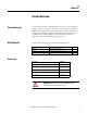
Chapter 20 Specifications Display Display Type Viewing Area 128 x 64 LCD with yellow-green backlighting 57 x 30 mm (2.24 x 1.18 in.) Keypad Keypad Type Operation Force Operational Life Tactile embossed, domed keys, sealed membrane 453 g (16 oz) 1 million operations Communications Communication Protocol DeviceNet™ (125, 250, 500 Kbaud selectable) Electrical Input Voltage Range Input Power, typical Input current 11…25.0V DC 1.
Chapter 20 Specifications Dimensions Height Width Depth Weight Agency Approvals UL cUL CSA CE RoHS 82 116 mm (4.57 in) 70 mm (2.76 in) 15.5 mm (.67 in) 85 g (3 oz) 508 C22.2 No.
Appendix A DeviceNet™ Objects The following object classes are supported: Class 0x0001 0x0002 0x0003 0x0005 Identity Object Object Identity Message Router DeviceNet™ Connection CLASS CODE 0x0001 The following class attributes are supported for the Identity Object: Attribute ID 1 Access Rule Get Name Revision Data Type UINT Value 1 Each instance of the Identity Object contains the following attributes: Attribute ID 1 2 3 4 Access Rule Get Get Get Get 5 Get 6 7 Get Get Name Vendor Device T
Appendix A DeviceNet™ Objects The following common services are implemented for the Identity Object: Service Code 0x0E 0x05 0x10 Message Router Implemented for: Class No No No Service Name Instance Yes Yes No Get_Attribute_Single Reset Set_attribute Single CLASS CODE 0x0002 No class or instance attributes are supported. The message router object exists only to rout explicit messages to other objects.
DeviceNet™ Objects Connection Object Appendix A CLASS CODE 0x0005 No class attributes are supported for the Connection Object. Multiple instances of the Connection Object are supported for explicit UCMM connections.
Appendix A DeviceNet™ Objects Notes: 86 Rockwell Automation Publication 193-UM009B-EN-P - February 2013
Rockwell Automation Support Rockwell Automation provides technical information on the Web to assist you in using its products. At http://www.rockwellautomation.com/support, you can find technical manuals, technical and application notes, sample code and links to software service packs, and a MySupport feature that you can customize to make the best use of these tools. You can also visit our Knowledgebase at http://www.rockwellautomation.