
Quick Reference Owner manual

9
Publication 193-QR003B-EN-P - October 2009
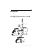
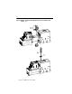
Control Terminals
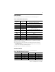
The following table defines the E3 Overload Relay control terminal designations.
➊ Features are available only with the E3 Plus Overload Relay (cat. nos. 193/592-EC2and 193/592-EC3).
➋ Available only on cat. nos. 193/592-EC5_ _.
➌ An earth ground connection to this terminal will assist in obtaining compliance with electromagnetic
compatibility requirements.
➍ The use of shielded cable is recommended for the positive PTC thermistor circuit to assist in obtaining
compliance with electromagnetic compatibility requirements.
➎ Available only on cat. nos. 193/592-EC3_ _ and 193/592-EC4_ _.
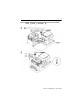
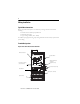
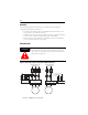
DeviceNet Terminals
The following table defines the DeviceNet connector terminal designations.
Table 2: Control Terminal Designation
Terminal
Designation
Reference Description
1 IN 1 General-purpose sinking input number 1
2 IN 2 General-purpose sinking input number 2
3 IN 3 General-purpose sinking input number 3 ➊➋
4 IN 4 General-purpose sinking input number 4 ➊➋
5V+
+24V DC supply for inputs
6V+
7 IN 5 General-purpose sinking input number 5 ➋
8 IN 6 General-purpose sinking input number 6 ➋
End Earth Ground ➌
13/14 OUT A Output A
23/24 OUT B Output B ➊➋
95/96 Trip Relay Trip Relay
IT1/IT2 PTC Thermistor (PTC) input ➊➍
S1/S2 — External ground fault sensor input ➋➎
Table 3: DeviceNet Terminal Designation
Terminal Signal Function Color
1 V- Common Black
2 CAN_L Signal Low Blue
3 Drain Shield Non-insulated
4 CAN_H Signal High White
5 V+ Power Supply Red