
Quick Reference Owner manual


10
Publication 193-QR003B-EN-P - October 2009
Grounding
The following grounding recommendations are provided to ensure electromagnetic
compatibility compliance during installation:
• The earth ground terminal of the E3 Overload Relay shall be connected to a solid
earth ground via a low-impedance connection
• Installations employing an external ground fault sensor shall ground the cable shield
at the sensor with no connection made at the E3 Plus Overload Relay
• The PTC thermistor cable shield shall be grounded at the E3 Plus Overload Relay
with no connection made at the opposite end
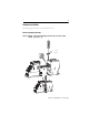
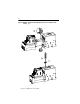
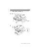
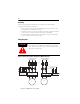
Wiring Diagrams
Figure 5: Three-Phase D.O.L & Single-Phase Wiring Diagrams
ATTENTION
!
When working on energized circuits, do not rely on the voltage and
current information provided by the E3 and E3 Plus for personal
safety. Always use a portable voltage or current measurement device
and measure the signal locally.
E3/E3Plus
L1 L2 L3
2/T1 4/T2 6/T3
E3/E3Plus
L1 L2 L3
2/T1 4/T2 6/T3
L1
2/T1 4/T2 6/T32/T1 4/T2 6/T3
2/T1 4/T2 6/T3
M
T1
E3/E3Plus
L1
2/T1 4/T2 6/T3
M
T1
T2
T3
S.C.P.D.
Three-Phase Direct-On-Line
Wiring Diagram
Single-Phase Full-Voltage
Wiring Diagram
T2
L2 L3
L2
E3/E3Plus
L1 L2 L3
Voltage Input Module
(For 193/592-EC5 only)
L1 L2
Voltage Input Module
(For 193/592-EC5 only)